Storage system and method of controlling of feeding power to storage system

a storage system and power technology, applied in the field of storage system and a control method of feeding power to a storage system, can solve the problems of reducing the amount of power a storage system consumes, the inability of the storage system to control the feeding power of a plurality of disk drives within the storage system independently, and the difficulty of reducing the access time from the host system

Active Publication Date: 2008-05-01
RAKUTEN GRP INC
View PDF5 Cites 54 Cited by
  • Summary
  • Abstract
  • Description
  • Claims
  • Application Information

AI Technical Summary

Benefits of technology

[0021]An embodiment of the present invention, further comprising the step of stopping the feeding of power to a storage device which is not predicted as the next access target storage device and which has been accessed least recently by a host system from among the storage devices.
[0022]An embodiment of the present invention, further comprising the steps of

Problems solved by technology

Hence, the larger the number of disk drives connected within a storage system increases, the greater the amount of power a storage system consumes.
Consequently, in a prior art such as this, controlling the power reduction of a stora

Method used


Image

  • Storage system and method of controlling of feeding power to storage system
  • Storage system and method of controlling of feeding power to storage system
  • Storage system and method of controlling of feeding power to storage system

Examples


first embodiment

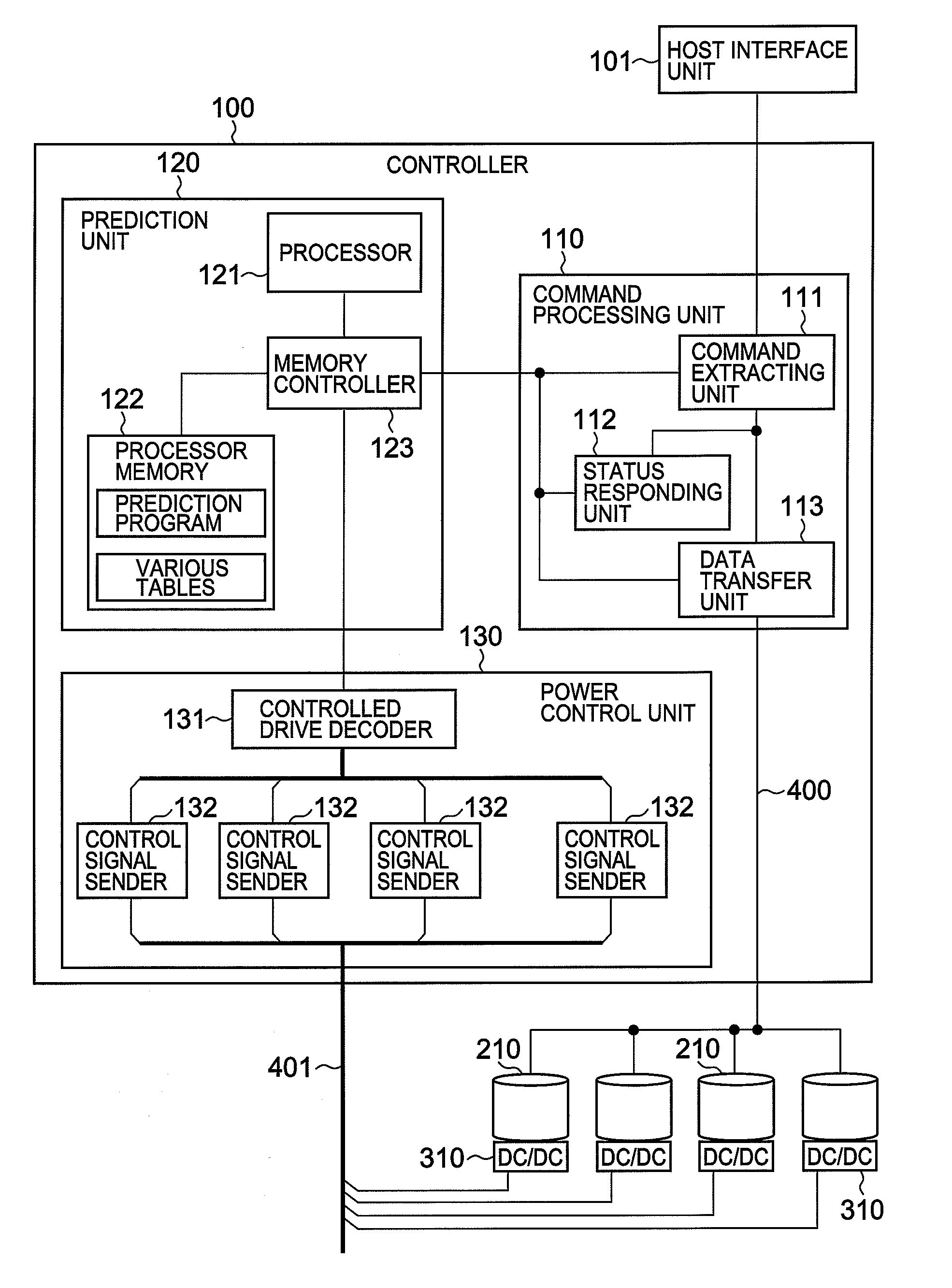
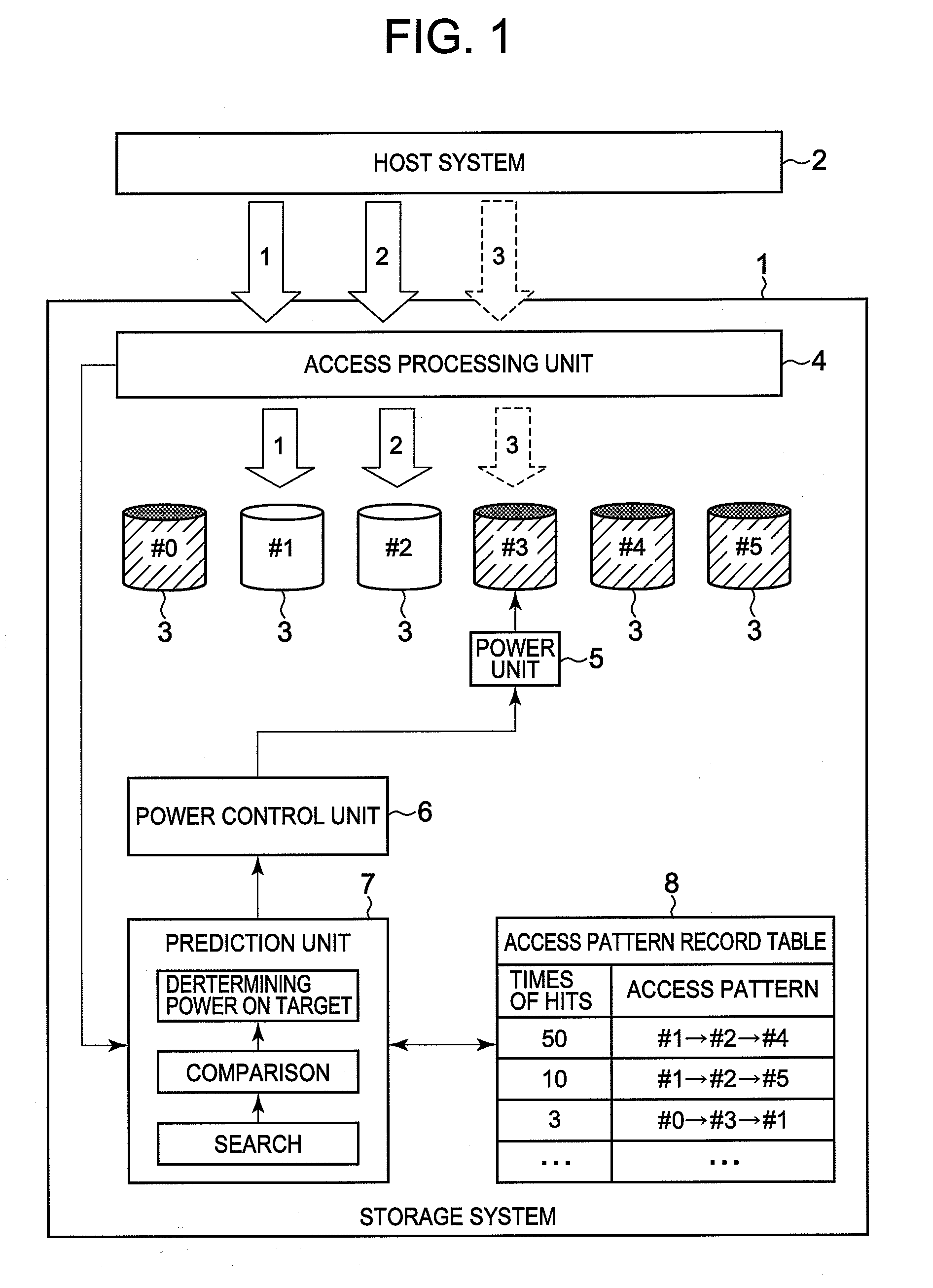
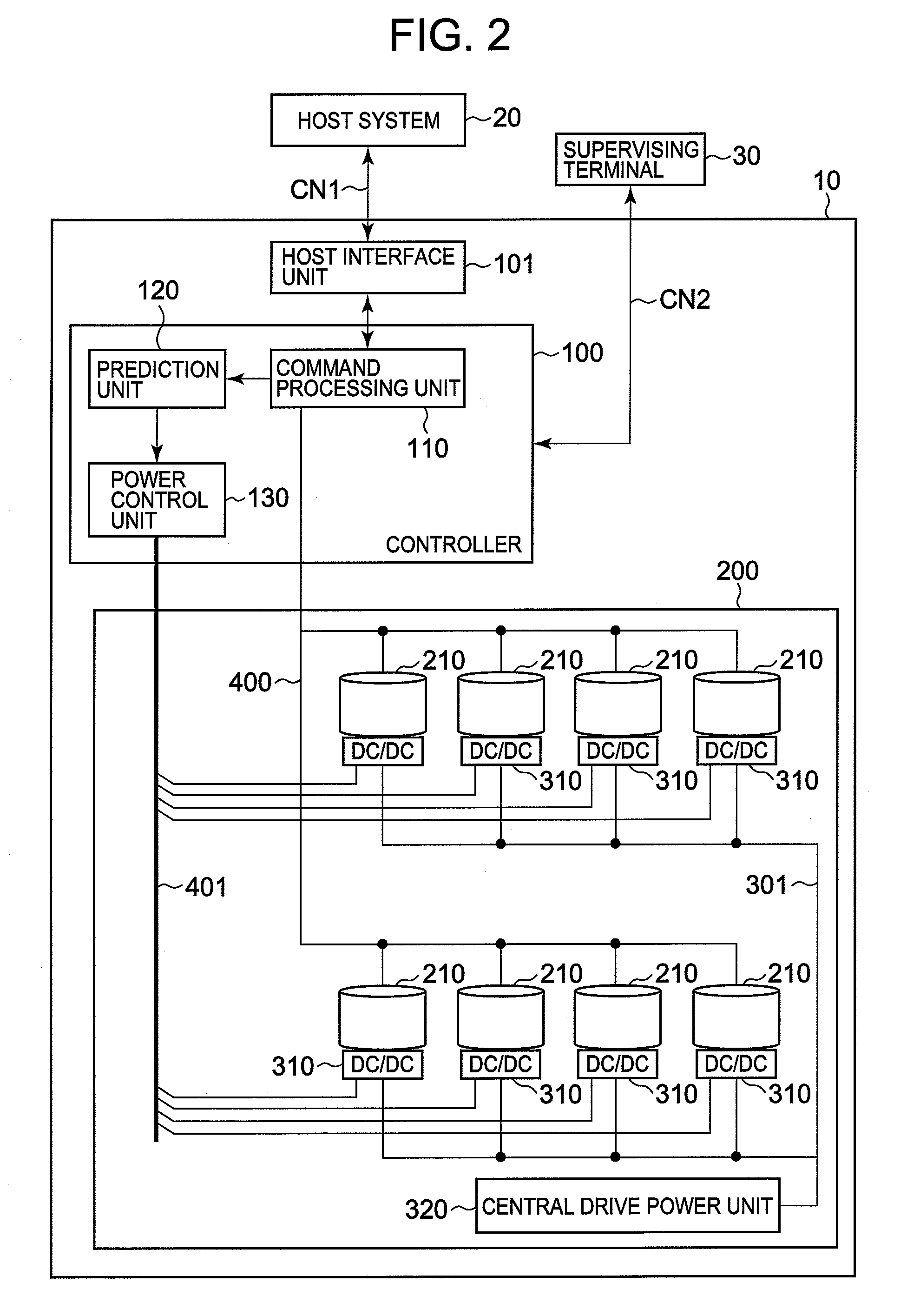
[0057]FIG. 2 is a drawing showing an overall structure of a storage system. The entire system, for example, consists of a storage system 10, a host system 20, and a supervising terminal 30. The correspondent relationship with FIG. 1 will be described in advance. The storage system 10 corresponds to the storage system 1 in FIG. 1, the host system 20 corresponds to the host system 2 in FIG. 1, the disk drives 210 corresponds to the disk drives 3 in FIG. 1, the command processing unit 110 corresponds to the access processing unit 4 in FIG. 1, the power control unit 130 corresponds to the power control unit 6 in FIG. 1, the prediction unit 120 corresponds to the prediction unit 7 in FIG. 1, and the local power units 310 correspond to the power unit 5 in FIG. 1, respectively.

[0058]Host system 20, as mentioned above, is a server, mainframe or other such computer systems, and, for example, is connected to host interface unit 101 via a communications network CN1, such as a SAN (Storage Area...

second embodiment

[0117]A second embodiment of the present invention will be explained on the basis of FIGS. 9 and 10. The following embodiments, to include this embodiment, correspond to variations of the first embodiment. In this embodiment, power-on timing is delayed as much as possible by over all managing not only the sequence in which access is requested, but also access time intervals, thereby realizing even greater power savings.

[0118]FIG. 9 is a drawing showing an access pattern record table T5 utilized by a storage system 10 according to this embodiment. This table T5 has the same part as table T3 shown in FIG. 5, and, for example, is configured by making a record number I51, times of hits I52, history length I53, and access sequence I54 correspond to one another.

[0119]The difference with the table T3 shown in FIG. 5 is that, in addition to the sequence I54A in which logical volumes have been accessed, the time interval I54B of adjacent accesses is included in the access sequence I54 indica...

third embodiment

[0124]A third embodiment will be explained on the basis of FIGS. 11 and 12. In this embodiment, the feeding of power to the respective disk drives 210 is individually controlled in accordance with a schedule preset by a user.

[0125]FIG. 11 is a drawing showing a storage system, which comprises a storage system 10 according to this embodiment. A schedule setting unit 31 is provided in the supervising terminal 30. The schedule setting unit 31 can be realized as software, which provides a function for a user to set a power control-related schedule (the power-on schedule shown in FIG. 12).

[0126]FIG. 12 is a flowchart showing the process for setting a power-on schedule. When a user starts up the schedule setting unit 31 of the supervising terminal 30, a power-on schedule setting window 500 is displayed on the terminal screen (S50). The user utilizes this setting window 500 to input a power-on target logical volume 230 and power-on time (S51).

[0127]The power-on schedule setting window, for...


PUM


Abstract

A storage system of the present invention saves power consumption of the storage system and enhances responsiveness by predicting a disk drive that is to be accessed next on the basis of an access request from a host system, and promptly feeding power to the predicted disk drive. A prediction unit predicts the disk drive which is to be accessed next by the host system, by comparing a recent access request from the host system against a past access pattern that is registered in an access pattern record table. A power control unit feeds power from a power unit to the disk drive predicted by the prediction unit.

Description

CROSS-REFERENCE TO RELATED APPLICATIONS[0001]This application relates to and claims priority from Japanese Patent Application No. 2006-294309 filed on Oct. 30, 2006, the entire disclosure of which is incorporated herein by reference.BACKGROUND OF THE INVENTION[0002]1. Field of the Invention[0003]The present invention relates to a storage system and a method of controlling of feeding power to a storage system.[0004]2. Description of the Related Art[0005]A storage system comprises a storage unit, which connects a large number of hard disk drives in an array, and provides a logical storage area (logical volume) to a server or other such host computer (hereinafter “host system”). To enforce reliability and so forth, the storage system provides a host system with a redundant storage area based on RAID (Redundant Array of Independent Disks).[0006]Now then, the data being managed by companies and so forth is increasing day by day. The more the amount of the data is increasing, the larger t...

Claims


Application Information

Patent Timeline
IPC IPC(8): G06F1/00
CPCG06F1/3221Y02B60/1246Y02B60/1278G06F1/3287G06F3/0689G06F3/0625Y02B60/1282G06F1/3268G06F3/0634Y02D10/00
Inventor SHIMADA, KENTARO
Owner RAKUTEN GRP INC
Why Eureka
Try Eureka