Combustion chamber shield for hot water heaters

a technology for hot water heaters and shields, which is applied in the direction of drum steam boilers, combustion processes, lighting and heating apparatus, etc., can solve the problems of heat loss, chambers become very hot, and substantial heat loss through the lower skirt of the housing

Inactive Publication Date: 2004-03-02
MICLAU S R I
View PDF6 Cites 17 Cited by
  • Summary
  • Abstract
  • Description
  • Claims
  • Application Information

AI Technical Summary

Benefits of technology

It is a feature of the present invention to provide a shield for the combustion chamber of a hot water hea

Problems solved by technology

With known gas-fired hot water heaters using combustion chambers, there is a substantial heat loss through the lower skirt of the housing which is disposed adjacent the combustion chamber of the water heater and through the lower end portion of the housing.
Also, the insulation between the lower skirt a

Method used


Image

  • Combustion chamber shield for hot water heaters
  • Combustion chamber shield for hot water heaters
  • Combustion chamber shield for hot water heaters

Examples


Embodiment Construction

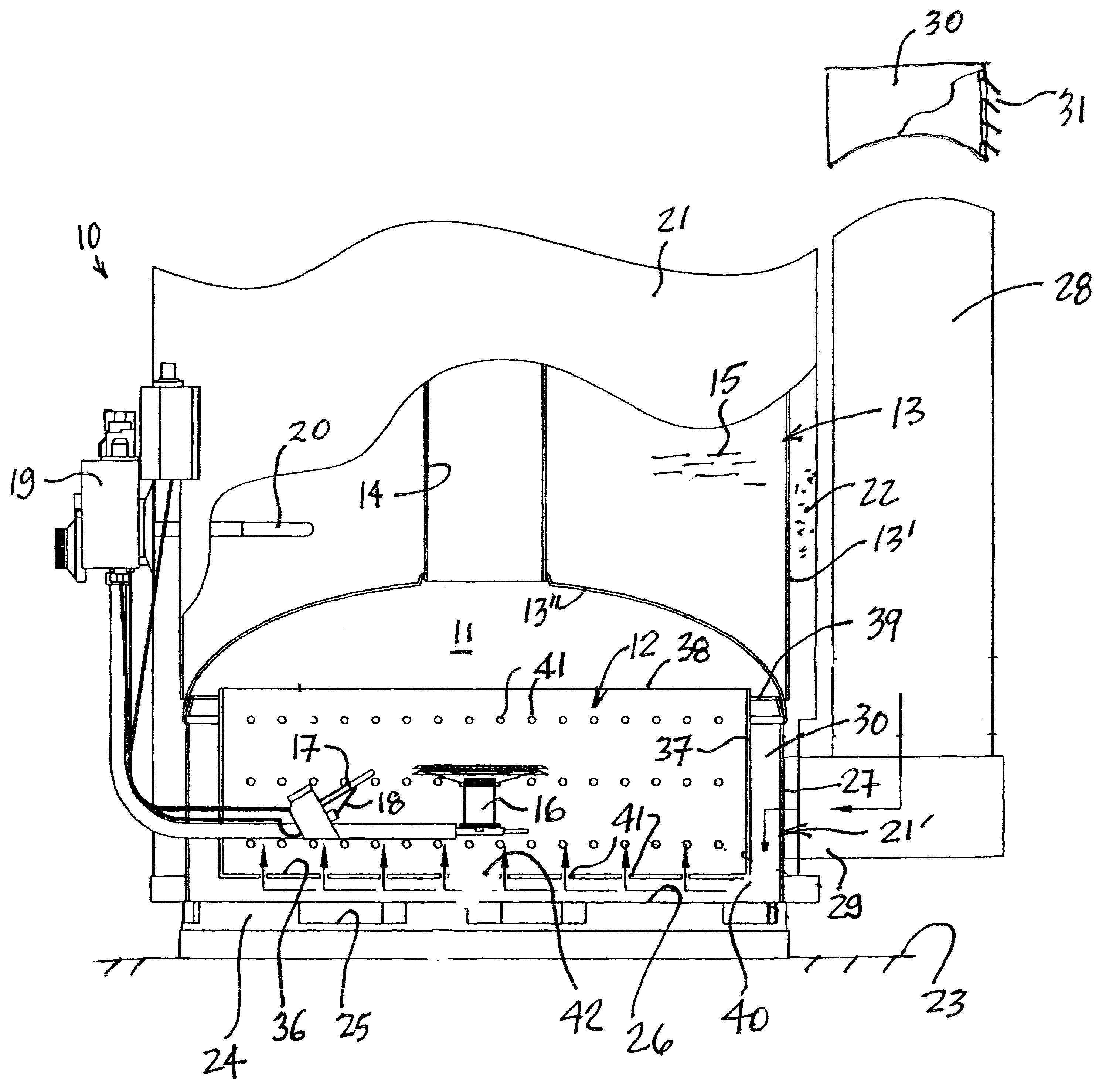
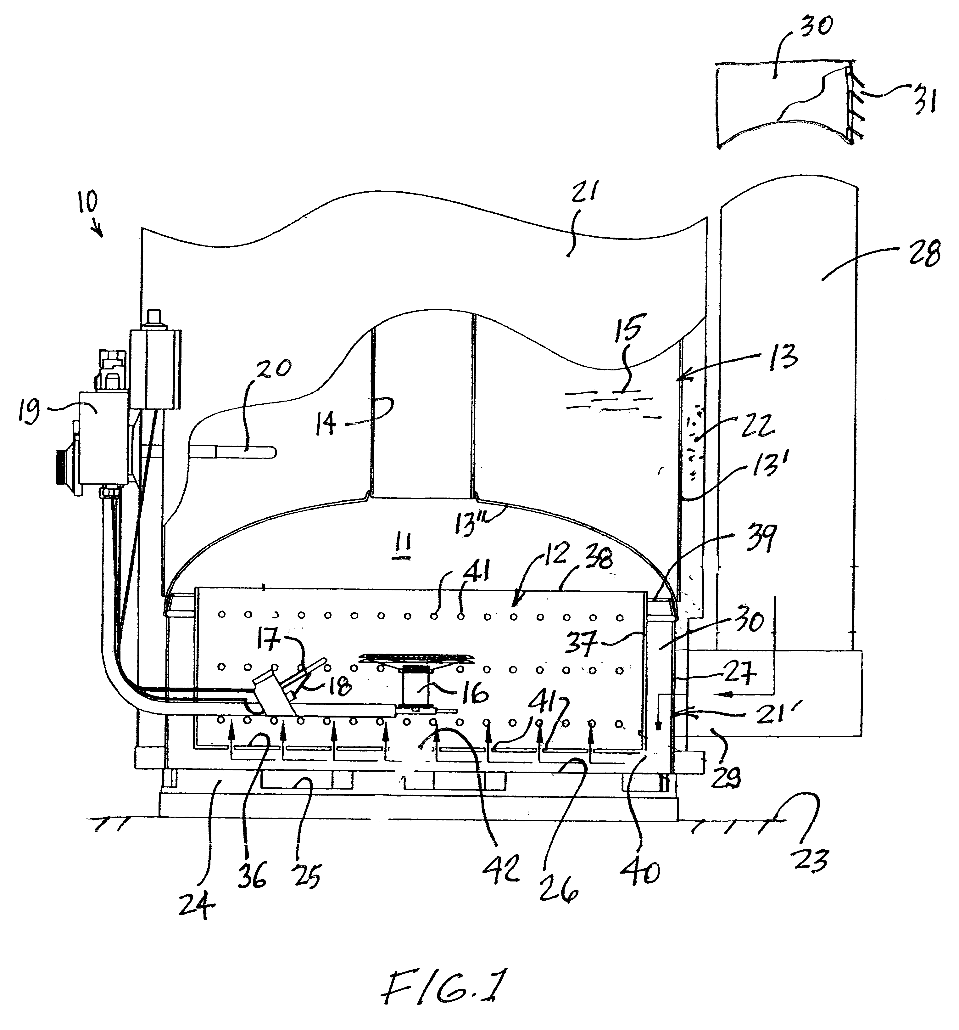
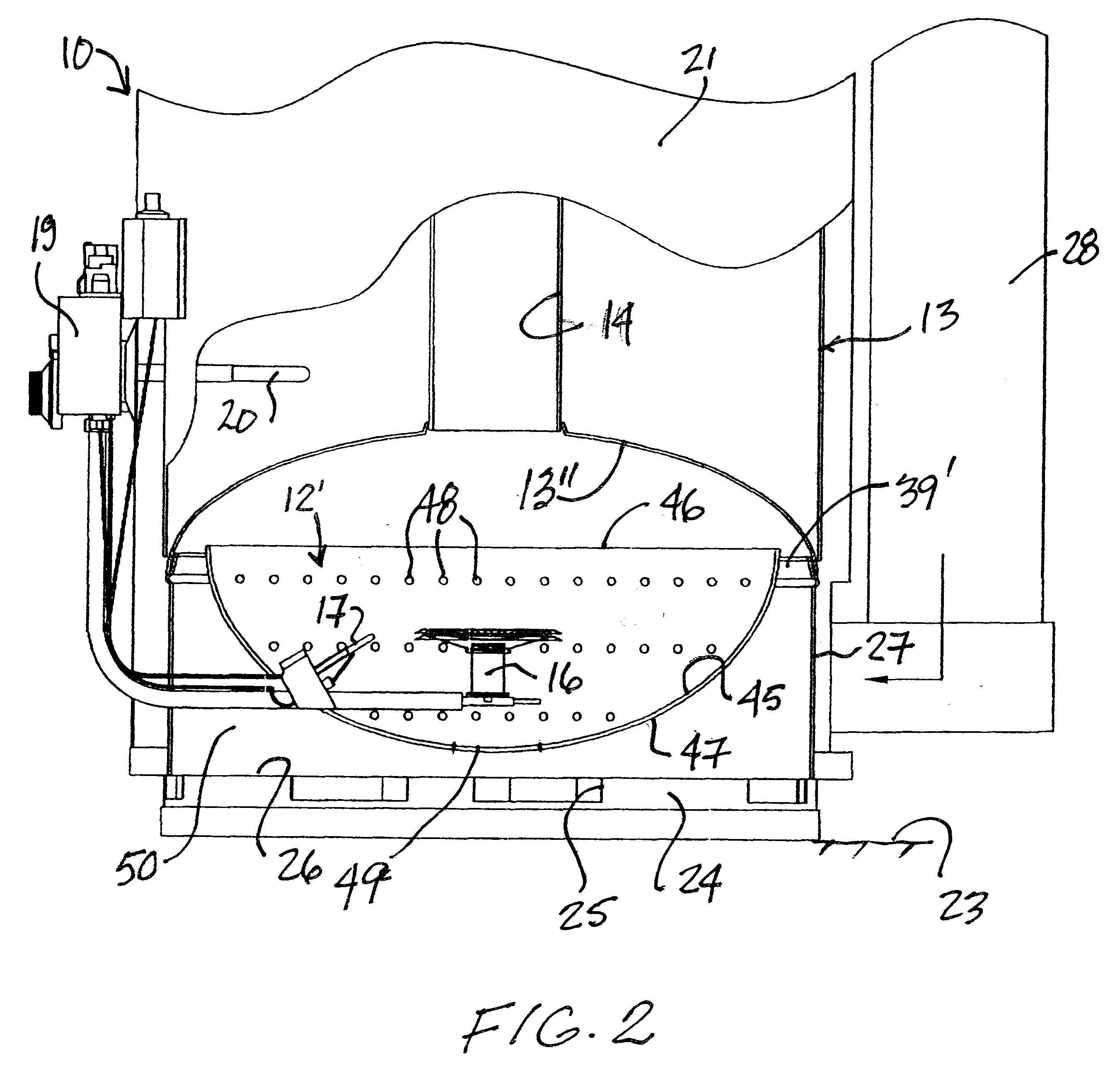
Referring to the drawings, and more particularly to FIG. 1, there is shown generally at 10 a lower portion of a hot water heater and which illustrates the basic component parts thereof and more particularly its lower combustion chamber 11 which is provided with the heat shield 12 of the present invention. As hereinshown, the hot water heater has an inner casing 13 which is of elongated cylindrical shape and provided with a central flue 14 extending therethrough and exhausting at a top end in a manner well known in the art. Water 15 to be heated is contained within the inner casing 13 and dispensed therefrom, as is also well known in the art.

The hot water heater as herein illustrated is a gas-fired hot water heater and its sealed combustion chamber 11 is provided with a burner 16 and a pilot 17 which is provided with an igniter 18 to kick-start the burners 16. A control 19 controls the burner and is provided with a water temperature sensor 20 to effectuate this control. This is also ...


PUM


Abstract

A shield for a combustion chamber of a hot water heater is described. The combustion chamber is a sealed or not combustion chamber and the metal heat shield encircles and is spaced about the burner and pilot which is located in the combustion chamber. The shield is also spaced from the skirt and a bottom wall of the combustion chamber. The shield is further provided with apertures to permit passage of air supplied by an air supply duct. The shield provides for heat concentration on a lower heat transfer wall of the inner casing containing the water to be heated. The shield also reduces heat loss through the skirt and the bottom end wall of the combustion housing.

Description

The present invention relates to a shield for a combustion chamber of a gas-fired hot water heater whereby to provide heat concentration in the combustion chamber and on a lower heat transfer wall of the inner casing and also to reduce heat loss through the skirt and the bottom end of the water heater.With known gas-fired hot water heaters using combustion chambers, there is a substantial heat loss through the lower skirt of the housing which is disposed adjacent the combustion chamber of the water heater and through the lower end portion of the housing. With the new designs of sealed combustions, combustion air is supplied through a vertical duct which is in registry with a supply hole provided in the skirt and therefore the insulation in that area is reduced. Also, the insulation between the lower skirt and the outer casing is not sufficiently thick and this results in heat loss as sealed combustion chambers become very hot. Accordingly, there is excessive heat loss through the sk...

Claims


Application Information

Patent Timeline
IPC IPC(8): F24H9/18F24H1/20
CPCF24H9/1881F24H1/205
Inventor LESAGE, CLAUDE
Owner MICLAU S R I
Why Eureka
Try Eureka