Torque sensor

a torque sensor and magnetic field technology, applied in the direction of magnetostrictive devices, measuring devices, instruments, etc., can solve the problems of limited use of this sensor, less attractive for many applications, and restricted use of this sensor

Inactive Publication Date: 2004-03-09
ABB (SCHWEIZ) AG
View PDF10 Cites 25 Cited by
  • Summary
  • Abstract
  • Description
  • Claims
  • Application Information

AI Technical Summary

Benefits of technology

The object with the present invention is to provide a magnetostrictive sensor for measuring a torque in a shaft, which sensor is simple to provide on a shaft, provides good measurement results and is possible to provide on existing shafts substantially independent of the manufacturing material of the shaft.
This object is achieved by the magnetostrictive sensor of the initially mentioned kind which is characterised in that said surface pattern is formed by a second layer of a non-magnetostrictive material comprising a low resistivity. Because of eddy currents induced in the first layer, the applied magnetic field decreases (is damped) exponentially with the distance from the surface of the first layer. By choosing a sufficiently thick layer, the properties of the sensor will be dominated by the first layer material and not by the shaft material. By providing a first layer of a suitable thickness on the circumferential surface of the shaft, the influence of the shaft material on the measurement results of the sensor becomes more or less negligible. Thereby, the sensor may be provided on substantially all kinds of shafts and independent of shaft material. Such a magnetostrictive sensor also obtains a good function with a first layer of a material having a relatively low permeability.
According to a preferred embodiment of the present invention, said second layer is provided on the first layer. By providing a second layer of a non-magnetostrictive material on the first layer, the surface pattern which provides the magnetostrictive region with anisotropic properties is obtained. Advantageously, said first layer has a continuous extension in said region. Such a first layer is simple to provide at the same time as it forms a continuous and even underlying surface on which the second layer may easily be provided. Furthermore, such a continuous first layer minimises stress concentrations in the magnetostrictive region. According to an alternative embodiment, the first layer is provided with a non-continuous extension on the surface of the shaft and in that at least any portion where the first layer does not abut the surface of the shaft, the second layer is provided on the surface of the shaft. By providing both the first layer and the second layer on the surface of the shaft in said surface pattern, the magnetostrictive region may obtain a substantially even surface layer.
According to another preferred embodiment said first and second layers are arranged to be applied by an application method which essentially does not introduce heat. By avoiding high temperatures, the strength and tolerances of the load-carrying shaft are not influenced. A suitable application method which does not introduce heat is plating. There exists at least two applicable plating methods for plating metals on an existing element, namely bath plating and selective plating, but also chemical (electro-less) plating is applicable. Advantageously, the surface of the shaft is arranged to be subjected to a pre-treatment before said layers are applied. By such a pre-treatment, which may comprise blasting, shot peening, grinding, pickling, doping or chemical strike, the first layer obtains a sufficient bond to the surface of the shaft. Advantageously, said applied layers are arranged to be subjected to an additional post-plating treatment. Such a treatment may be mechanical and / or thermal for improving the strength of the layers and the properties of the sensor.

Problems solved by technology

The use of this sensor is restricted to measure torque in shafts which consist of materials having good magnetostrictive properties.
Since drive shafts only in exceptional cases are manufactured of material having good magnetostrictive properties, the use of this sensor is restricted.
Consequently, the method requires both mechanical treatment and heat treatment of the load-carrying shaft, which makes it less attractive for many applications.
The second layer must be magnetostrictive for the function of the sensor and a considerable disadvantage is that the second layer also must have a high permeability.
However, providing a first layer thickness which is greater than two skin depths usually contributes very little with respect to the accuracy of measurement since, at two skin depths, only a very small amount of the applied magnetic field penetrates into the underlying shaft material.
A greater layer thickness implies in general a higher manufacturing cost.

Method used


Image

  • Torque sensor
  • Torque sensor
  • Torque sensor

Examples


Embodiment Construction

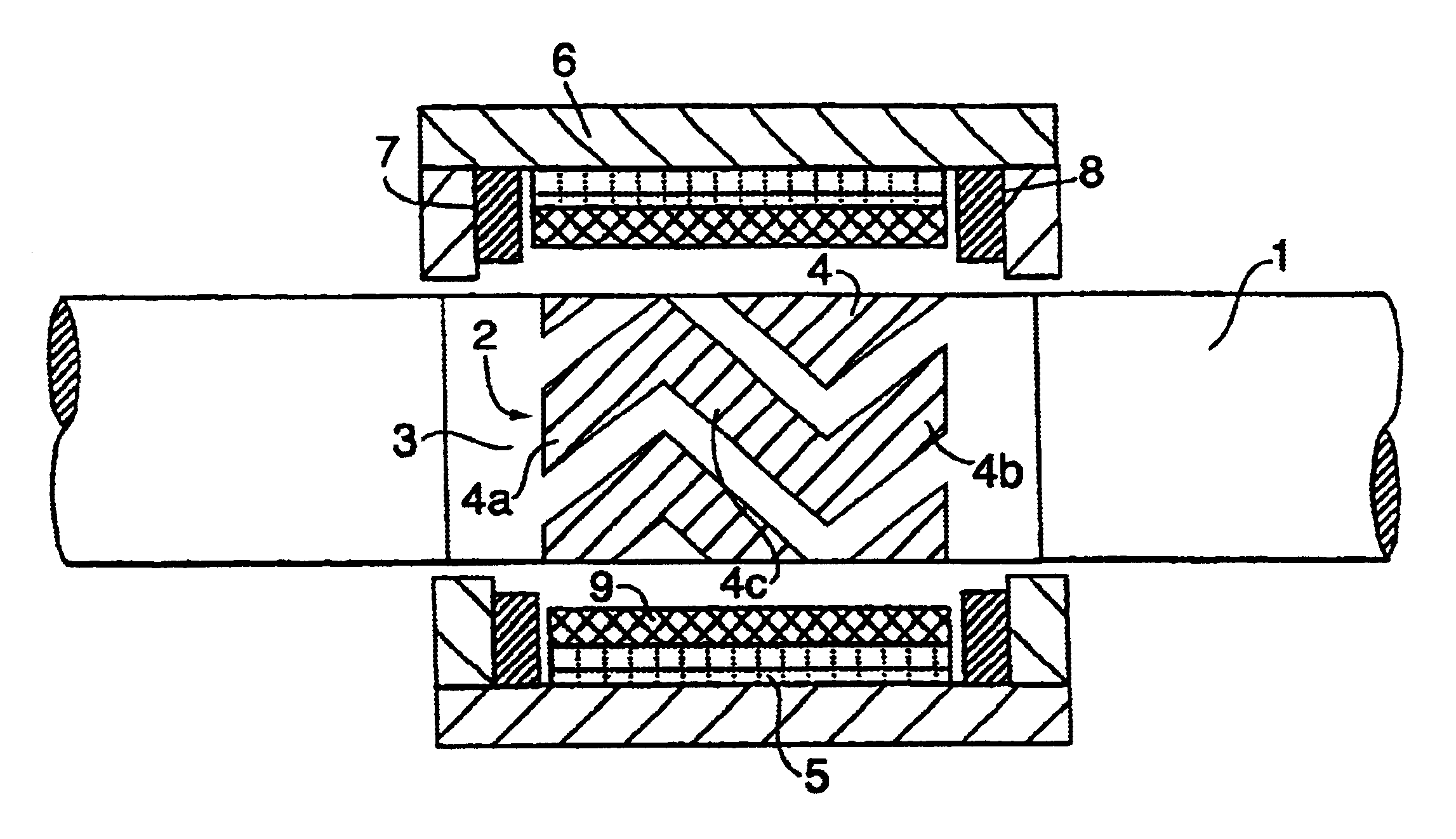
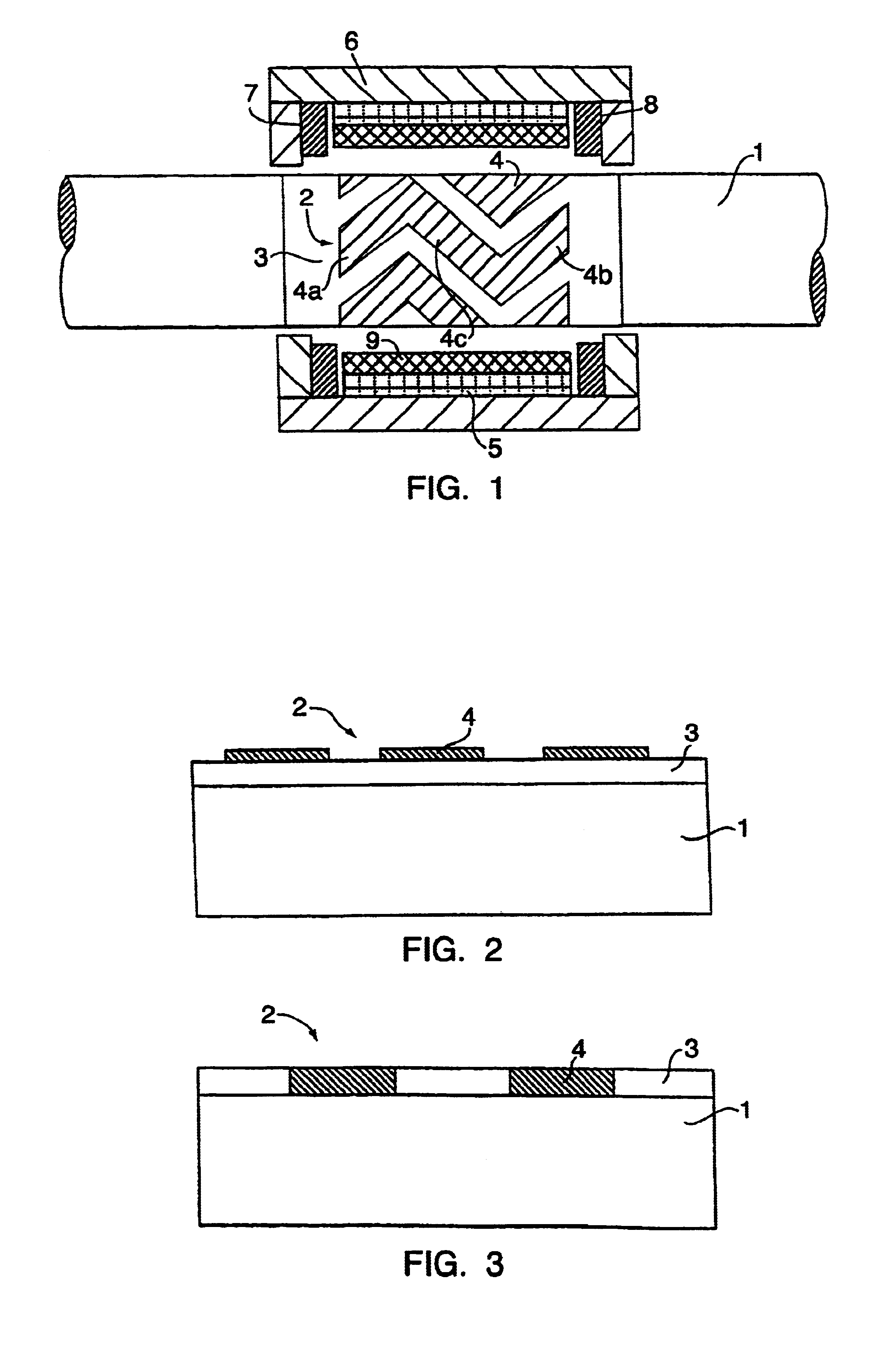
FIG. 1 shows a rotatable shaft 1, which is arranged to transmit a torque in any kind of mechanical transmission. The shaft 1 may here consist of a substantially arbitrary material, which meets the mechanical demands required on the shaft 1 as a transmission element with reference to hardness, strength and geometry. To be able to measure the size and direction of a torque in the shaft 1, a magnetostrictive sensor has been provided in a suitable place along the extension of the shaft 1. In this case, the magnetostrictive sensor comprises a magnetostrictive region 2 provided on the shaft 1, which has an extension on the circumferential surface of the shaft. The magnetostrictive region 2 comprises a first layer 3 of a magnetostrictive material, which has a substantially continuous extension and thickness in said region 2. Advantageously, the first layer 3 comprises nickel but it may also comprise iron, cobalt and other materials which have suitable magnetostrictive properties. A second ...


PUM

PropertyMeasurementUnit
angleaaaaaaaaaa
angleaaaaaaaaaa
angleaaaaaaaaaa

Abstract

The present invention relates to a magnetostrictive sensor for measuring a torque in a shaft. The sensor comprises at least one active magnetostrictive region on the shaft, a surface pattern in the magnetostrictive region such that it obtains anisotropic properties, a first means arranged to generate a magnetic field varying in time in the magnetostrictive region and a second means arranged to sense variation in the permeability in the magnetostrictive region. Said magnetostrictive region comprises a first layer of a magnetostrictive material which is provided on the surface of the shaft and that said surface pattern is formed by a second layer of a non-magnetostrictive material comprising a low resistivity.

Description

BACKGROUND OF THE INVENTION AND PRIOR ARTThe present invention relates to a magnetostrictive sensor for measuring torque in a shaft, wherein the sensor comprises at least one active magnetostrictive region of the shaft, a surface pattern on the magnetostrictive region such that it obtains anisotropic properties, a first means arranged to generate a magnetic field varying in time in the magnetostrictive region and a second means arranged to sense variations in the permeability in the magnetostrictive region, and wherein said magnetostrictive region comprises a first layer of a magnetostrictive material provided on the surface of the shaft.Such magnetostrictive sensors are known and exist in a number of different embodiments. Usually, magnetostrictive sensors according to the above comprise first means comprising a first winding provided in a yoke and extending around the magnetostictive region of the shaft. A current varying in time is arranged to be supplied to the first winding suc...

Claims


Application Information

Patent Timeline
Patent Type & Authority Patents(United States)
IPC IPC(8): G01L3/10H01L41/12
CPCG01L3/102G01L3/103G01L3/105
Inventor WALLIN, CHRISTERLING, HANSHASSEL, LARS
Owner ABB (SCHWEIZ) AG
Why Eureka
Try Eureka