Spring loaded feed mechanism for paintball loader

a paintball loader and spring technology, applied in the field of paintball loaders, can solve the problems of paintball jams, paintball guns and accessories have increased in performance and complexity, and existing paintball guns are limited in how fast they can accelerate to a rapid firing ra

Inactive Publication Date: 2004-03-09
PNC BANK NAT ASSOC
View PDF12 Cites 82 Cited by
  • Summary
  • Abstract
  • Description
  • Claims
  • Application Information

AI Technical Summary

Benefits of technology

In one aspect, the present invention is a feed mechanism for use on a paintball loader. The feed mechanism includes an axial member longitudinally positioned about a center axis. The axial member is rotated by a motor. In addition, a spring communicates with the axial member. The spring compresses during rotational deceleration of the axial member and assists in the rotational acceleration of the axial member.

Problems solved by technology

The paintball gun and accessories have increased in performance and complexity over the years.
However, existing paintball guns are limited in how fast they can accelerate to a rapid firing rate by the performance of the motor driving the paintball loader.
But such abrupt changes in the loader's rotation rate oftentimes results in paintball jams, as well as subjecting the paintball loader to undesirable forces.
The braking mechanism rapidly slows the rotation of the drive cone, which subjects the drive cone to undesirable forces.
These forces cause wear and tear on the paintball loader.
Obviously, the time necessary to accelerate to a high rotational rate is limited by the torque provided by the motor driving the drive cone.
Over-driving of a feed mechanism may also introduce undesirable forces on the paintballs located within the loader, resulting in paintball breakage or jams.

Method used


Image

  • Spring loaded feed mechanism for paintball loader
  • Spring loaded feed mechanism for paintball loader
  • Spring loaded feed mechanism for paintball loader

Examples


Embodiment Construction

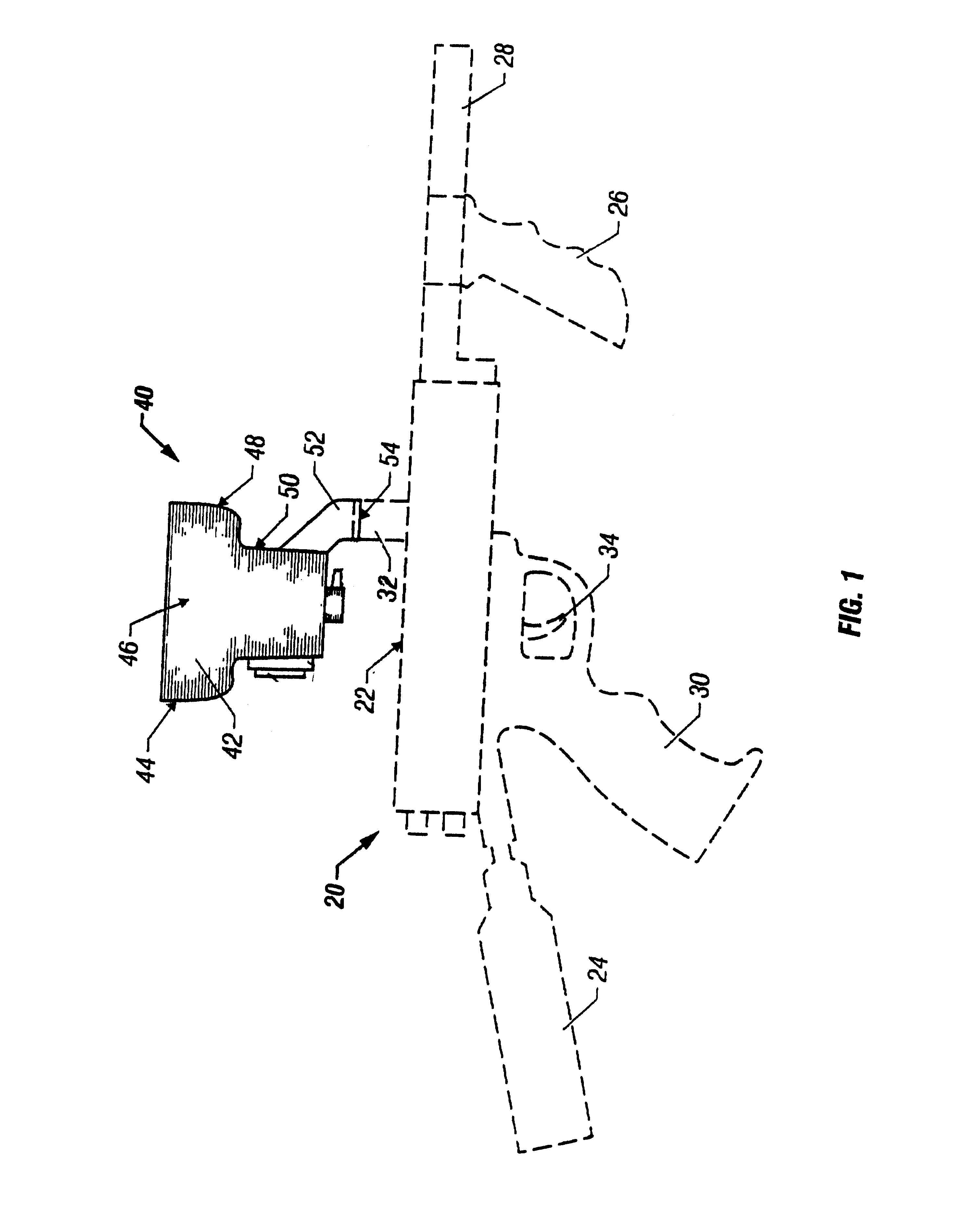
A spring-loaded feed mechanism for use on a paintball loader for rapidly delivering paintballs is disclosed. FIG. 1 is a side elevational view of a rapid feed paintball loader 40 constructed in accordance with the teachings of the present invention and operatively attached to a representative paintball gun 20 illustrated in phantom. The paintball gun 20 includes a main body 22, a compressed gas cylinder 24, a front handgrip 26, a barrel 28, and a rear handgrip 30. The paintball gun also includes an inlet tube 32 leading to a firing chamber (not shown) in the interior of the main body and a trigger 34. The front handgrip projects downwardly from the barrel and provides an area for gripping by an operator of the paintball gun. The compressed gas cylinder is typically secured to a rear portion of the paintball gun. The compressed gas cylinder normally contains CO.sub.2, although any compressible gas may be used.

In operating the paintball gun 20, the trigger 34 is squeezed, thereby actu...


PUM


Abstract

A spring-loaded feed mechanism for a paintball loader. The feed mechanism includes an inner spool and an outer spool. A torsion spring is positioned between the inner and outer spools. The outer spool includes a pressure wall, from which the torsion spring is located on one end of the spring. A retaining wall is attached to the inner spool and is located at the opposite end of the torsion spring. When an operator of a paintball gun using the spring-loaded feed mechanism discontinues firing paintballs, the feed mechanism is stopped. Simultaneously, during the deceleration of the feed mechanism, the torsion spring is compressed, which allows the mechanical energy of the rotating feed mechanism to be stored within the compressed spring. When the operator desires to fire the paintball gun, the feed mechanism is accelerated to the requisite rotational speed. The compressed spring is release, thereby allowing the spring to assist in accelerating the feed mechanism to the necessary rotational speed.

Description

1. Technical Field of the InventionThis invention relates to paintball loaders, and more particularly, to a spring-loaded feed mechanism feeding paintballs into a paintball gun.2. Description of Related ArtGames utilizing paintball guns have increased in popularity over the past few years. Players of these games normally shoot paintballs at each other through paintball guns. The paintballs are gelatin-covered spherical capsules filled with paint. During play of the game, the players on each team advance toward each other. A player is eliminated from the game when the player is hit by a paintball fired from an opposing player's gun. When the paintball hits a player, a "splat" of paint is left on the player.Normally an existing paintball loader includes a housing which is placed on an upper portion of a paintball gun. The housing is shaped to hold a large quantity of paintballs. At the bottom of the housing is an outlet tube through which the paintballs drop by the force of gravity. T...

Claims


Application Information

Patent Timeline
Patent Type & Authority Patents(United States)
IPC IPC(8): F41B11/00F41B11/02G06F3/14G09B23/00G09B23/28
CPCF41B11/57F41B11/53G09B23/28
Inventor CHRISTOPHER, JAMES T.GODDARD, CHRIS T.
Owner PNC BANK NAT ASSOC
Why Eureka
Try Eureka