Combination weighing apparatus having a weighing device base, to which a plurality of weighing devices are fixed, that is directly fixed to a stand

a technology of weighing device and weighing device body, which is applied in the direction of weighing device details, instruments, measurement devices, etc., can solve the problems of increasing the weight of the whole apparatus, deteriorating the weighing accuracy of the subject to be weighed, and increasing the cost, so as to achieve the effect of increasing the mass of the apparatus and low cos

Inactive Publication Date: 2004-03-09
ANRITSU SANKI SYSTEM CO LTD
View PDF11 Cites 10 Cited by
  • Summary
  • Abstract
  • Description
  • Claims
  • Application Information

AI Technical Summary

Benefits of technology

An object of the present invention is to provide a combination weighing apparatus which solves the problems mentioned above and is particularly structured such that a weighing accuracy with respect to a subject to be weighed is not affected by internal and external vibrations, without increasing a mass of the apparatus as a whole, and a vibration sensor for compensating an influence due to the external vibration can be obtained at a low cost.
In accordance with the combination weighing apparatus, it is possible to vertically move the lower side separated casing along the circular column by rotating the lower side separated casing so as to easily open and close the casing in a vertical direction, so that it is easy to inspect and maintain the drive sources and the weighing devices within the casing;

Problems solved by technology

However, in the conventional combination weighing apparatus having the structure mentioned above, since the respective weighing device bases 11, 11, . . . are provided between the feeder base 15 fixed to the upper portion of the hollow polygonal tube shaped casing 2 fixed on the stand 1 and the stand 1, the respective weighing devices 10, 10, . . . are little affected by the vibration of the respective vibrating devices 16, 16, . . . , leading to a disadvantage that a weighing accuracy with respect to the subject to be weighed is deteriorated.
Further, since the respective weighing device bases 11, 11, . . . are mounted to the side wall 2a of the hollow casing 2 at every weighing devices 10, 10, . . . , a stable operation of the respective weighing devices 10, 10, . . . depends upon a rigidity of the casing 2, so that it is necessary to firmly form the casing 2 at that degree for stabilizing the weighing operation, whereby there is a disadvantage that the weight is increased as a whole of the apparatus.
Further, it is necessary to provide a vibration sensor for compensating for the effects of the external vibration in the installing place of the stand 1, however, in the conventional apparatus shown in FIG. 34, since the respective weighing device bases 11, 11, . . . are provided in every weighing device 10, 10, . . . , it is necessary to mount the vibration sensors (not shown) to every weighing device base 11, 11, . . . , which is a disadvantageous as the cost is increased.
Accordingly, in the case that the subject to be weighed is particularly a food, in the combination weighing apparatus mentioned above in which the opening and closing lid is opened and closed at a significantly high speed, and the subject to be weighed is violently dropped and discharged, there is a risk that the fine powder of the subject to be weighed which is supplied and dropped down gradually attaches and accumulates on the whole of the combination weighing apparatus such as the hoppers, the casing and the like during continued use, so as to be an obstacle, or bacteria breed on the subject to be weighed which is attached and accumulated in the respective portions or the subject to be weighed is spoilt.
Further, as mentioned above, in the conventional combination weighing apparatus, due to the complex structure, there is a risk that it is hard to clean and a food sanitation is deteriorated, so that it is significantly inconvenient.
Further, at a time of water cleaning, the water easily enters within the window 18 through the portion between the outer peripheral end surface of the mounting plate 19 and the side wall 2a, and there is a risk that the internal motor M and the weighing device W cannot be used.
Further, since it is necessary to remove the motor M and the weighing device W together with the mounting plate 19 by removing the mounting plate 19 in the manner mentioned above at a time of inspection or maintenance the motor M and the weighing device W within the casing 2, the operation is very troublesome.

Method used


Image

  • Combination weighing apparatus having a weighing device base, to which a plurality of weighing devices are fixed, that is directly fixed to a stand
  • Combination weighing apparatus having a weighing device base, to which a plurality of weighing devices are fixed, that is directly fixed to a stand
  • Combination weighing apparatus having a weighing device base, to which a plurality of weighing devices are fixed, that is directly fixed to a stand

Examples


first embodiment

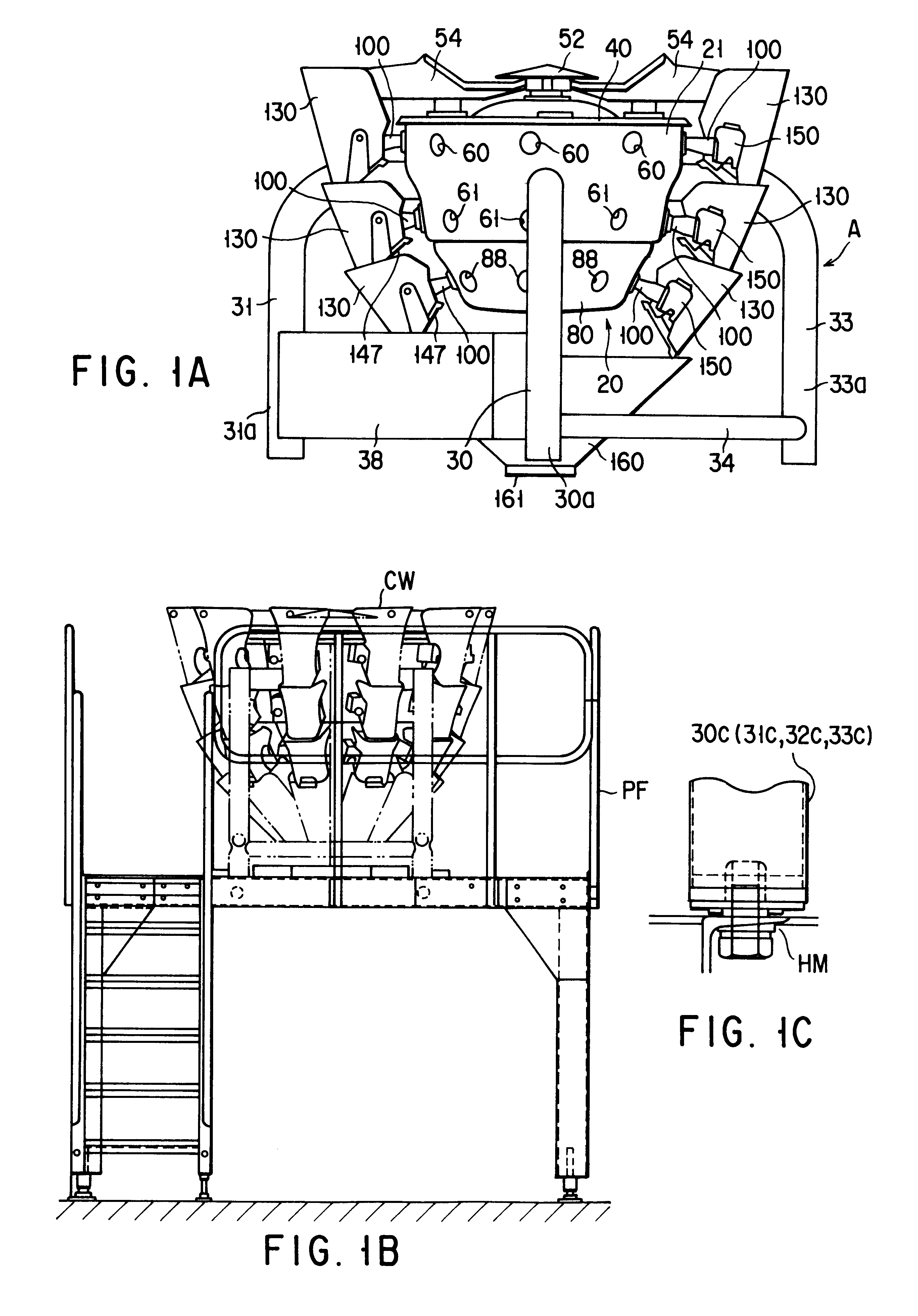
FIGS. 1A to 17 show a whole structure and structures of respective portions in a combination weighing apparatus in accordance with a first embodiment of the present invention.

In this case, FIG. 1B shows a placing state of the combination weighing apparatus in accordance with the first embodiment of the present invention.

Further, FIG. 1C shows a partial view of the placing state of the combination weighing apparatus in accordance with the first embodiment of the present invention.

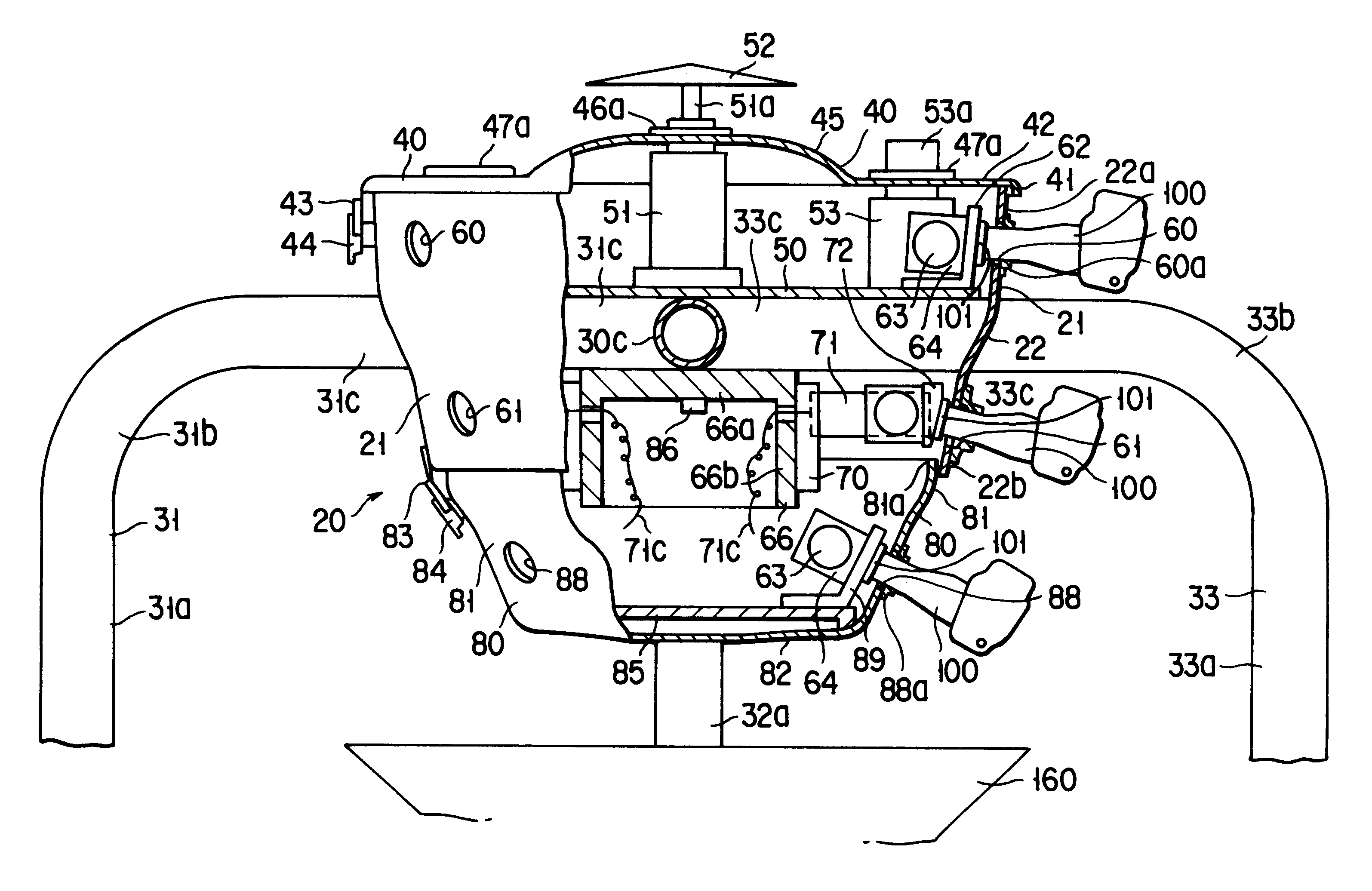
At first, a casing 20 is supported by a stand A comprising four supporting columns 30, 31, 32 and 33.

A number of hoppers 130, 130, . . . are provided on an outer periphery of the casing 20 so as to be arranged in a cylindrical shape.

The casing 20 is provided with a cylindrical casing main body 21 in which an upper end and a lower end are opened and a lower half portion is formed so as to have a smaller diameter than that of an upper half portion.

The casing main body 21 is supported by four supporting columns...

second embodiment

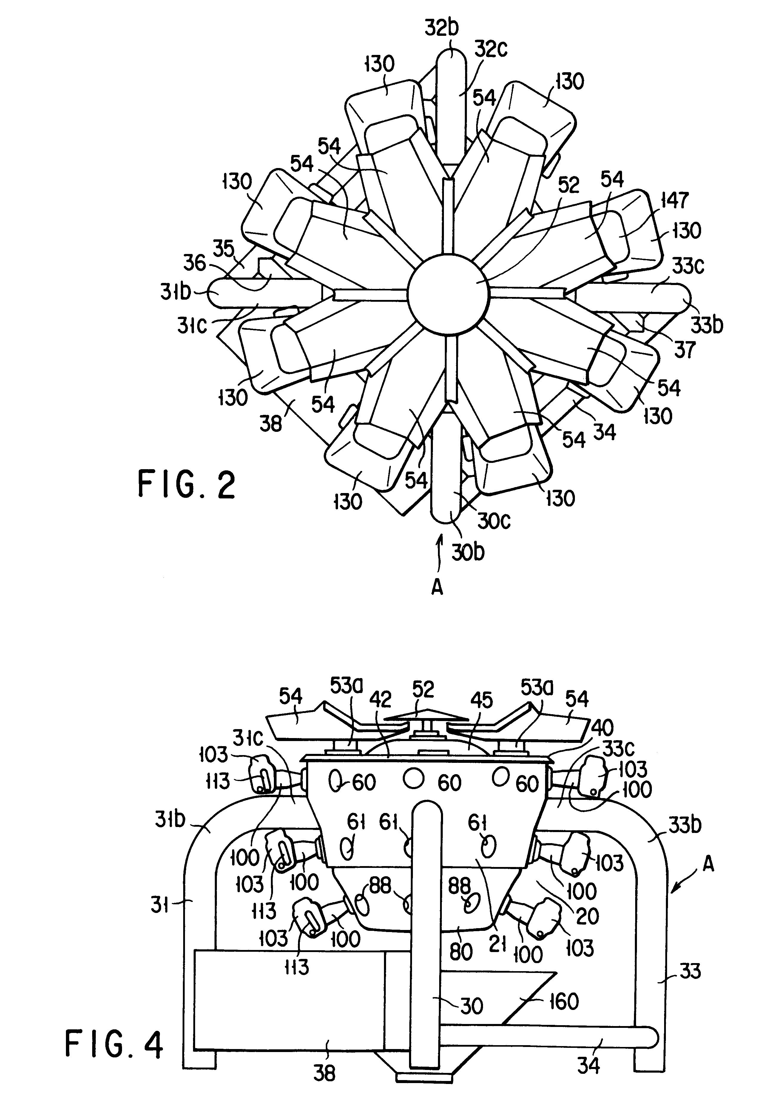
In the first embodiment mentioned above, as shown in FIG. 3, there is exemplified a case that the supporting columns 30, 31, 32 and 33 constituting the stand A are formed in a cylindrical shape.

On the contrary, in this second embodiment, as shown in FIG. 18, the stand A is constituted by supporting columns 230, 231, 232 and 233 structured such that leg portions 230a, 231a, 232a and 233a formed in a rectangular column shape and vertically standing up from a contact surface and supporting portions 230c, 231c, 232c and 233c including horizontal portions are vertically arranged.

third embodiment

Further, in the third embodiment, as shown in FIG. 19, four rectangular supporting columns 330, 331, 332 and 333 constituting the stand A are fixed by a suitable means such as welding, bolts or the like so that front end portions of supporting portions 330c, 331c, 332c and 333c including respective horizontal portions alternately form rectangular spaces B.

In this case, a weighing base 266 is constituted by a hollow tube body 267 formed in a polygonal shape corresponding to a number in a circumferential direction of the hoppers and having a large thickness, and a polygonal flange portion 268 disposed at an upper end thereof.

Further, the flange portion 268 may be fixed to the rectangular portion at the front end of the supporting portions 330c, 331c, 332c and 333c including the horizontal portions in the supporting columns 330, 331, 332 and 333.

In accordance with the structure mentioned above, it becomes further easy to fix the weighing device base 266 to the stand A, and it is possib...


PUM


Abstract

In a combination weighing apparatus, a plurality of feeders supply a subject to be weighed. A plurality of weighing hoppers receive the subject to be weighed which is supplied by a plurality of feeders. A plurality of weighing devices weigh the subject to be weighed which is received in each of the weighing hoppers. A plurality of weighing devices are fixed to the weighing base. Stands are provided in a circumferential direction at a predetermined interval, the stands respectively have leg portions standing up from a placing surface and supporting portions including horizontal portions connected to the leg portions, and the horizontal portions of the supporting portions are constituted by a plurality of metal supporting columns connected to each other in center portions. The weighing base is directly fixed to a lower surface of the center connecting portions of the stands.

Description

The present invention related to a combination weighing apparatus, and more particularly to a combination weighting apparatus structured such that a weighing accuracy with respect to a subject to be weighed is not affected by internal and external vibrations, and to a vibration sensor that compensates for the influence of the vibrations, obtainable at low cost and without an increase in overall weight of the apparatus.Further, the present invention relates to a combination weighing apparatus, and more particularly to a combination weighing apparatus structured such that the subject to be weighed and fine powder thereof hardly attach thereto, and maintenance and cleaning operations can be easily carried out during normal operations.As is well known, conventionally, a combination weighing apparatus is employed for bagging foods, that is, goods individually having uneven mass, for example, potato chips, peanuts, fruit, sausages and the like at a predetermined mass or a substantially pr...

Claims


Application Information

Patent Timeline
Patent Type & Authority Patents(United States)
IPC IPC(8): G01G19/387G01G19/393
CPCG01G19/393
Inventor WAKO, KAZUYOSHITANAKA, OSAMUASAI, EIJI
Owner ANRITSU SANKI SYSTEM CO LTD
Why Eureka
Try Eureka