Actuator and driving apparatus thereof

a technology of driving apparatus and actuator, which is applied in the direction of piezoelectric/electrostrictive/magnetostrictive devices, piezoelectric/electrostrictive/magnetostriction machines, piezoelectric/electrostrictive/magnetostriction device details, etc., to achieve the effect of reducing the cost of driving circuit or equipment, and generating high-voltage driving signals

Inactive Publication Date: 2004-03-09
MINOLTA CO LTD
View PDF13 Cites 47 Cited by
  • Summary
  • Abstract
  • Description
  • Claims
  • Application Information

AI Technical Summary

Problems solved by technology

However, when the piezoelectric actuator is used, for example, in a handy type equipment such as a camera, it is difficult to generate a high voltage driving signals for driving the piezoelectric devices, since electric energy of a battery is consumed by electric devices such as a motor for winding a film or for adjusting a position of a taking lens, an electromagnet for controlling shutter speed or for controlling a size of an aperture diaphragm, and so on.
Thus, a configuration of a driving signal generating circuit becomes more complex and larger than the conventional one, so that it is difficult to downsize the equipment using the piezoelectric actuator and to reduce the cost of the driving circuit or the equipment.
Thus, it is impossible to apply the conventional method to the piezoelectric device for increasing the output power thereof, since it is necessary to regard the polarization in the piezoelectric device.

Method used


Image

  • Actuator and driving apparatus thereof
  • Actuator and driving apparatus thereof
  • Actuator and driving apparatus thereof

Examples


first embodiment

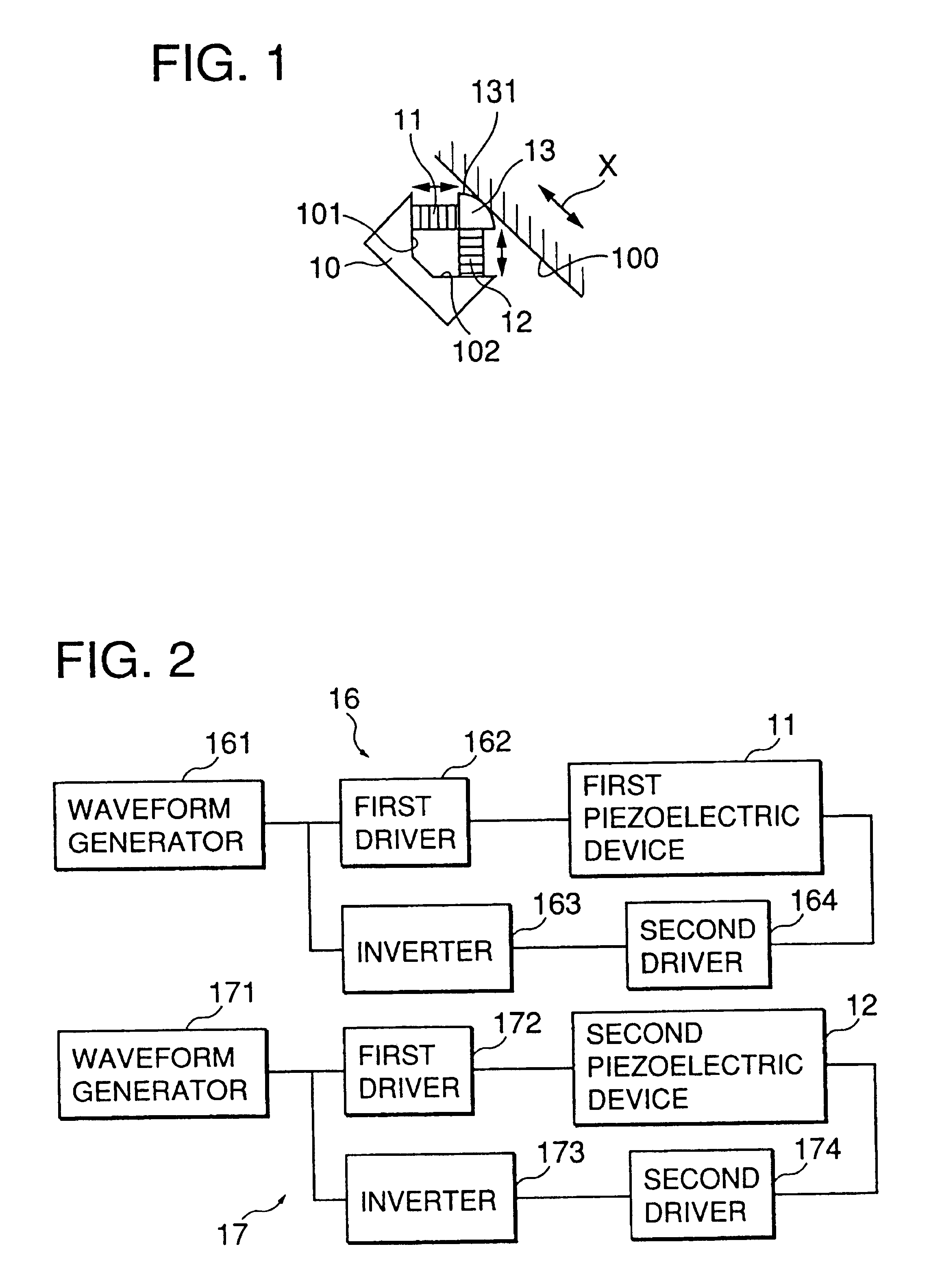
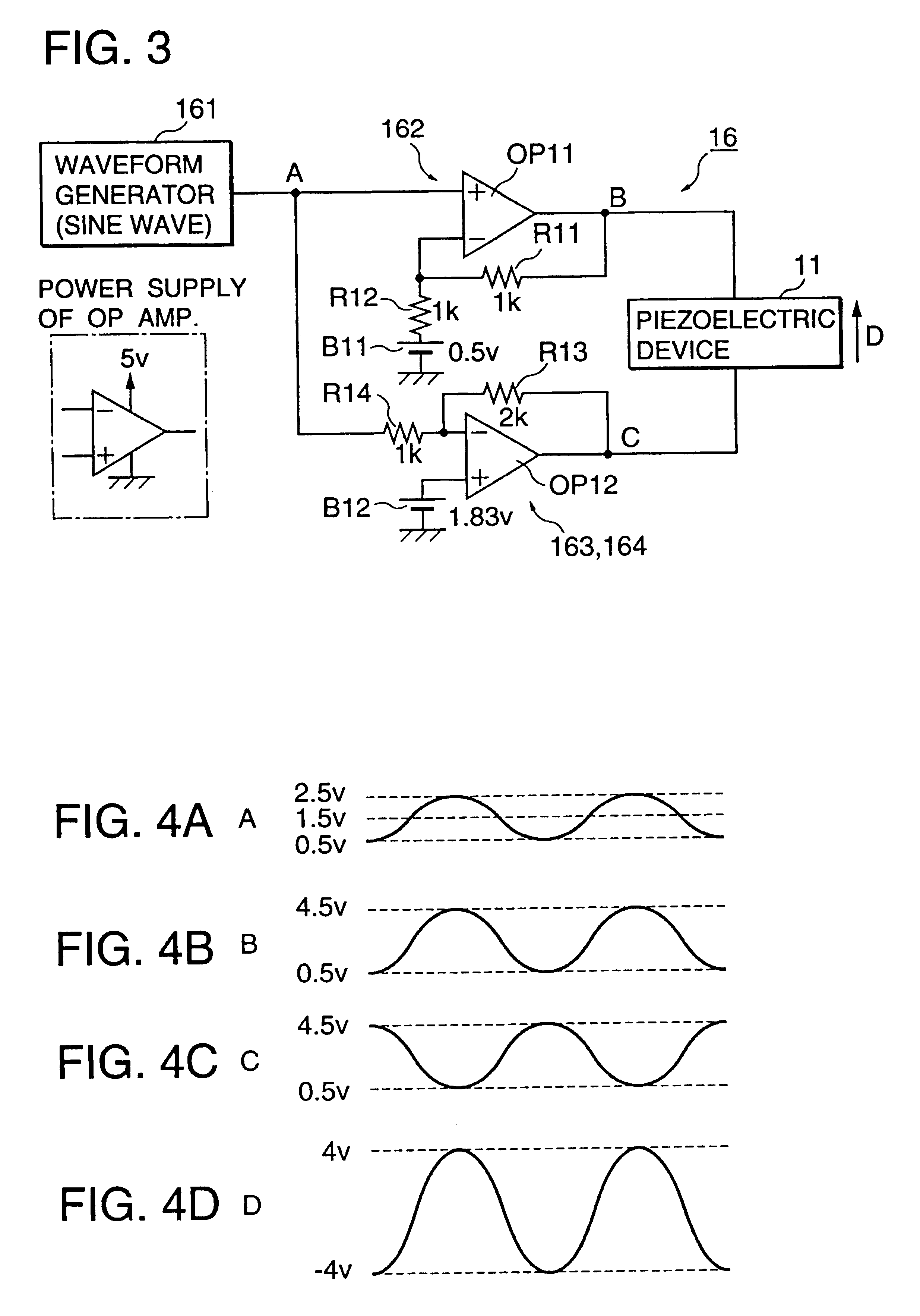
An actuator and a driving apparatus thereof in the present invention is described with reference to FIGS. 1, 2, 3 and 4A to 4C.

A configuration of a truss type piezoelectric actuator in the first embodiment is shown in FIG. 1. A base member 10 is fixed on a frame of a stationary apparatus (not shown in the figure). The base member 10 has two contacting faces 101 and 102 which will cross at right angle if they are extended. A first piezoelectric device 11 and a second piezoelectric device 12 respectively have substantially the same rectangular parallelepiped shape and the same configuration. Base ends of the first and second piezoelectric devices 11 and 12 are fixed on the contacting faces 101 and 102. Thus, the first and second piezoelectric devices 11 and 12 cross substantially at right angle. A driving member 13 is provided at crossing point of the first and second piezoelectric devices 11 and 12, and fixed on top ends of the first and second piezoelectric devices 11 and 12. As can...

second embodiment

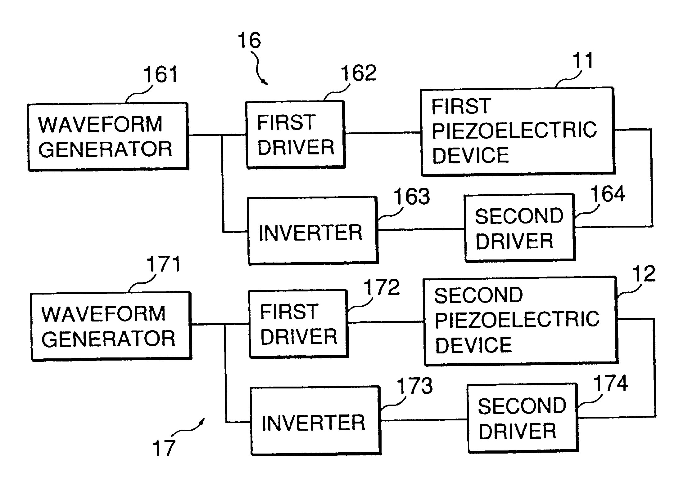
An actuator and a driving apparatus thereof in a second embodiment of the present invention is described with reference to FIGS. 5 and 6A to 6C. A configuration of a truss type piezoelectric actuator and a block diagram of a driving apparatus in the second embodiment are substantially the same as those in the first embodiment, so that the illustration and the description of them are omitted.

A circuit diagram of a first driving circuit 26 of the driving apparatus in the second embodiment is shown in FIG. 5. A second driving circuit 27 has substantially the same configuration as that of the first driving circuit 26, so that the illustration and the description of the second driving circuit 27 are omitted. A first driver 262 is configured by an operational amplifier OP21, resistors R21 and R22, and a constant voltage power supply B21. An inverter 263 and a second driving circuit 264 are integrally configured by an operational amplifier OP22, resistors R23 and R24, and a constant voltag...

third embodiment

An actuator and a driving apparatus thereof in a third embodiment of the present invention is described with reference to FIGS. 8, 9, 10, 11, 12, 13 and 14A to 14C.

A configuration of an impact type piezoelectric actuator in the third embodiment is shown in FIGS. 8 and 9. In FIG. 8, a rod shaped stationary member (first unit) 30a is hollowed except both ends and a center partition 301a for forming a first cavity 302a and a second cavity 303a. A piezoelectric device 31a is provided in the first cavity 302a in a manner so that a direction of piling up of the ceramic thin plates coincides with an axis of the stationary member 30a and the base end of the piezoelectric device 31a is fixed on the stationary member 30a. A sliding rod 32a and a slider (second unit) 33a which is engaged with outer cylindrical face of the sliding rod 32a are provided in the second cavity 303a. The sliding rod 32a penetrates holes serving as bearings of the sliding rod 32a and formed on the center partition 301...


PUM


Abstract

In a piezoelectric actuator, a first driving signal amplified a predetermined sine wave is a applied to a piezoelectric device in a direction parallel to a polarization direction thereof. A second driving signal having a negative phase with respect to the first driving signal which is amplified the sine wave is applied to the piezoelectric device in a direction opposite to the polarization direction. Thus, the piezoelectric device is driven by a driving signal amplified the first or second driving signal double. Voltages of the first and second driving signals are much smaller than a voltage of invention of polarization of ceramic thin plates constituting the piezoelectric device.

Description

1. Field of the InventionThis invention relates to an actuator and a driving apparatus of the actuator, and especially relates to a truss type actuator or an impact type actuator for moving a driven object by utilizing a displacement generated in a piezoelectric device when an alternating driving voltage is applied thereto.2. Description of the Related ArtA piezoelectric device shows piezoelectric effect for expanding or contracting a displacement substantially in proportion to a level of a voltage when the voltage is applied in a direction parallel to the polarization direction thereof. Thus, a piezoelectric device is conventionally proposed to be used as an actuator for supplying a driving force to a driven object. The piezoelectric device used in the piezoelectric actuator is polarized in unidirectional. Electrodes are provided on both end faces of the piezoelectric device in the polarization direction thereof and output terminals of a driving circuit are connected thereto, so th...

Claims


Application Information

Patent Timeline
Patent Type & Authority Patents(United States)
IPC IPC(8): H01L41/00H01L41/04H01L41/09H02N2/00
CPCH02N2/0025H02N2/0075H02N2/025H02N2/067H02N2/026
Inventor OKADA, HIROYUKI
Owner MINOLTA CO LTD
Why Eureka
Try Eureka