Easy-to-mount optical connector system

a technology of optical connectors and connectors, which is applied in the field of easy-to-mount optical connector systems, can solve the problems of dangerous use of tools to obtain the exit of optical fibers from connectors, damage to the connection end of contacts, and pose problems

Inactive Publication Date: 2004-03-16
SOURIAU
View PDF5 Cites 14 Cited by
  • Summary
  • Abstract
  • Description
  • Claims
  • Application Information

AI Technical Summary

Benefits of technology

In the preferred embodiment, to ensure tight sealing at this rear sliding part, this part has at least two seals: an internal seal between an inner wall and the cable, and an outer seal between an outer wall and an inner wall of the channel of the connector in which the contact is mounted. Since these seals are preferably O-rings, they do not hamper the mobility of the rear part along the cable.

Problems solved by technology

This approach poses a problem.
It may be dangerous to use a tool to obtain the exit of the optical fiber from the connector.
Indeed, there is a risk that the tool might damage the connection end of the contact when it is inserted into the connection front face side.
Furthermore, this approach entails a substantial space requirement.
On the contrary, this approach raises problems of tight sealing in the channel in which the contact is placed.
On the whole, this prior art approach raises a first problem because it always imperatively necessitates specialized tooling in order to be able to disengage an optical contact of this kind from a channel of the connector into which it is inserted.
The solution described here about raises a second problem owing to the fact that the catching system is a small part mounted on the sleeve.
Now, since the sleeve is fixedly joined throughout its length with the optical cable that it surrounds, the mobility of this part is limited.
This makes it necessary to plan either for either very long sleeves which are difficult to mount or for handling operations in this very limited space just at the level of the connector.
This approach finally raises a third problem because, to be able to accurately fit the elastic clips into the groove of a channel of the complementary connector, it is necessary to place them so that they face each other.
Now, if this handling has to be done by means of a set of tools, then the teaching of this document does not make it possible, any more than the other approaches of the prior art, to resolve the problem of the easy mounting of an optical contact in its complementary connector.
However, this approach raises a problem because to ensure that the contact is kept in the connector, the contact additionally has a second internal pin extending radially with respect to the optical fiber and having to co-operate with a slot made in the inner wall of the complementary connector.
Indeed, this assembly requires excessively painstaking handling of the contacts and complementary connectors.
Finally, despite all the precautions, it would seem that, after a certain period of use, an optical connector of this kind is the site of transmission losses.
This cleaning is difficult, given the penetration depth of the ends of the optical fibers, especially in female contacts.

Method used


Image

  • Easy-to-mount optical connector system
  • Easy-to-mount optical connector system
  • Easy-to-mount optical connector system

Examples


first embodiment

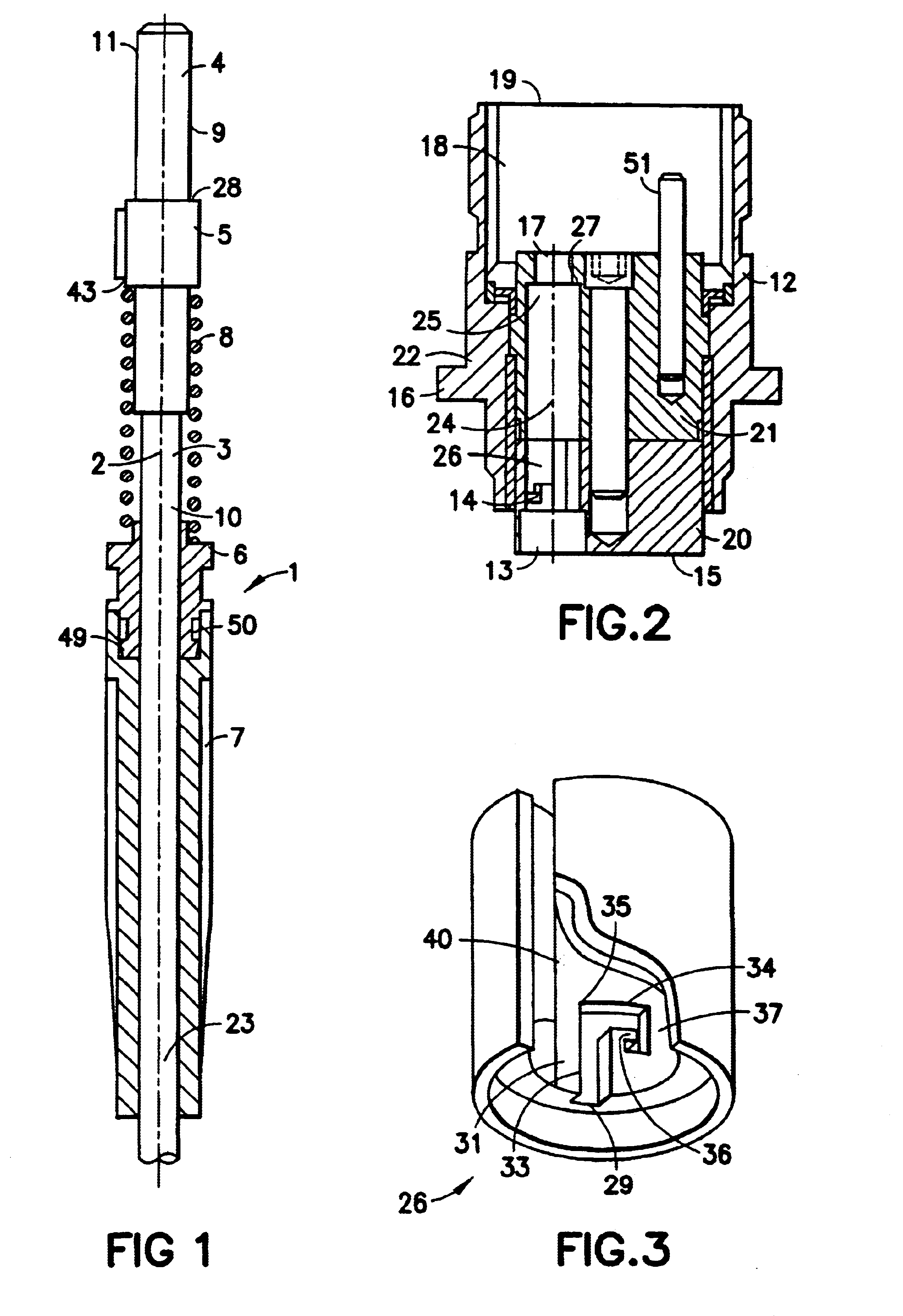
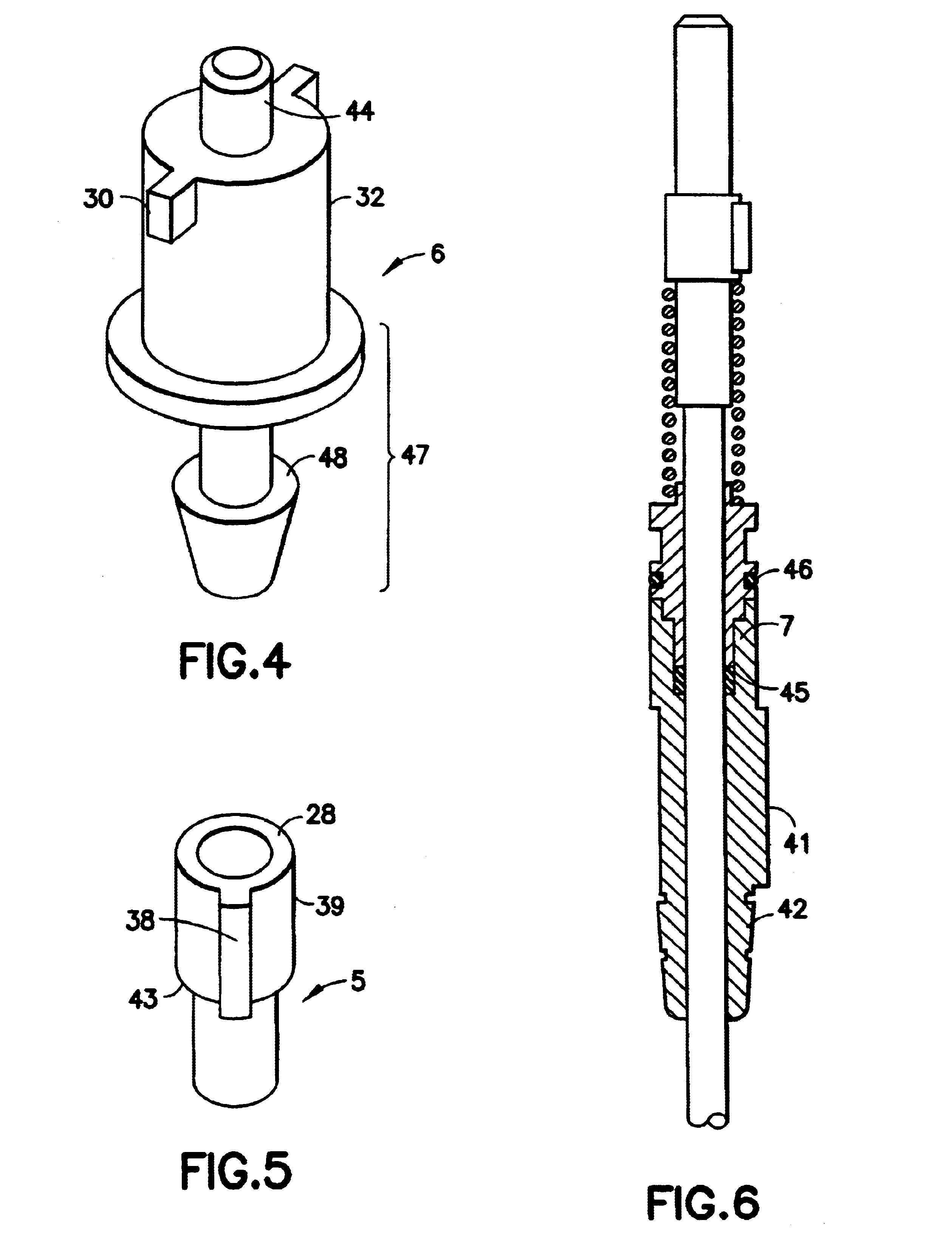
FIG. 4 shows a first embodiment in which the catch 6 has at least one external protruding feature 30 to form a bayonet designed to co-operate with the complementary raised feature 29 provided on an internal wall 31 of the channel 14. The protruding feature 30 corresponds for example to a parallelepiped or cylindrical pin raised perpendicularly to an external wall 32 of the catch 6. In a preferred embodiment, the complementary recess 29 is preferably formed in the rear channel portion 26.

For example, the complementary recess 29 forms an internal hollow in the inner wall 31, for example a guide way in which the protruding feature can move. The guide way 29 is elbowed. The guide way 29 preferably has a first section 33 and a second section 34, the second section 34 being separated in the first elbow 35 of the first section 33. The internal hollow 29, namely the first section 33, has a length along the central axis 24 that is limited in order to limit the penetration of the protruding f...

second embodiment

In a second embodiment, the catch 6 has a thread on its external rim that co-operates rotationally with a complementary thread on the inner wall 31 of the channel 14.

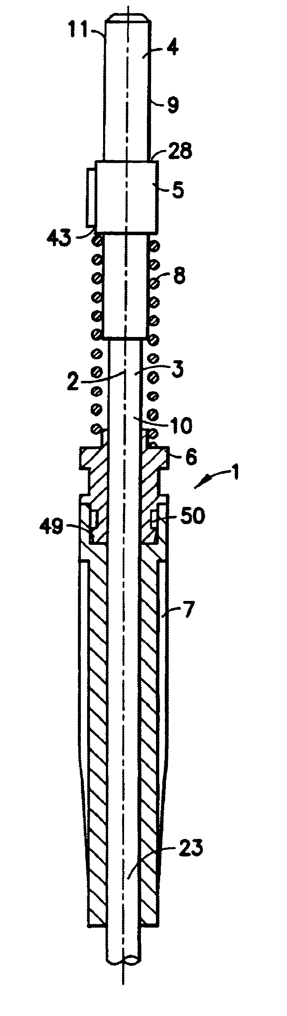
The catch 6 is fixedly joined to the rear part 7. In a first example, the catch 6 has a rear end 47 in the shape of a harpoon 48 to co-operate with an inner wall 49 of a cavity 50 of the rear part 7. In a second example, the inner seal 45 is positioned in such a way that it is stressed between the cable 3 and inner walls of the catch 6, which are themselves stressed, under the effect of the inner seal 45, against the inner walls 49 of the cavity 50 of the rear part 7.

The complementary connector 12 may furthermore have realignment means 51. A realignment means may extend into the receiving cavity 18 or else be a receiving cavity to receive the complementary alignment device of the complementary connector.


PUM


Abstract

An optical connector comprising a housing and a channel in this housing to receive an optical cable therein is preferably mounted in an optical contact having several parts, including a front part constituted by a connection ferrule and a sleeve used to prevent the rotation of the optical fiber inside the channel. The retention of the optical contact inside the channel is provided by a catch which has, for example, a bayonet mounted around the optical fiber that co-operates with a recess of an inner wall of the channel. A spring is positioned around the optical fiber to hold the bayonet in a return of the recess.

Description

1. Field of the InventionAn object of the present invention is a system of optical connectors, namely a system of connectors used for to interconnect optical fiber sections. The aim of the invention is to enable the easy mounting and dismounting of the optical connectors contained in such a system, while at the same time providing for the easy mounting of the optical contacts themselves to the ends of the cables, the optical contact being then inserted into these optical connectors2. Description of the Prior ArtThere is, in particular, a known optical contact in the prior art mounted at one end of a cable and having at least one elastic strip or clip on an external rim. In a preferred embodiment, the contact has several elastic clips positioned evenly and symmetrically with respect to an axis of symmetry of the cable. These elastic clips extend slightly beyond the external rim of the contact and may be folded down against this contact when the optical fiber is inserted into a channe...

Claims


Application Information

Patent Timeline
Patent Type & Authority Patents(United States)
IPC IPC(8): G02B6/38
CPCG02B6/389G02B6/3891
Inventor LECOMTE, FABRICEBADEAU, JEAN-MAXPIGNOT, PATRICK
Owner SOURIAU
Why Eureka
Try Eureka