
Buffer tube design for easy and reliable access in mid-span

a buffer tube and mid-span technology, applied in the direction of optics, fibre mechanical structures, instruments, etc., can solve the problems of affecting the access of placing tensile or compressive loads on the optical fibers residing therein, damaged or broken optical fibers, etc., and achieves the effect of reducing the difficulty of accessing optical fibers in mid-span, reducing the difficulty of tensile or compressive loads

Inactive Publication Date: 2004-03-16
ALCATEL LUCENT SAS
View PDF12 Cites 14 Cited by
  • Summary
  • Abstract
  • Description
  • Claims
  • Application Information

AI Technical Summary

Benefits of technology

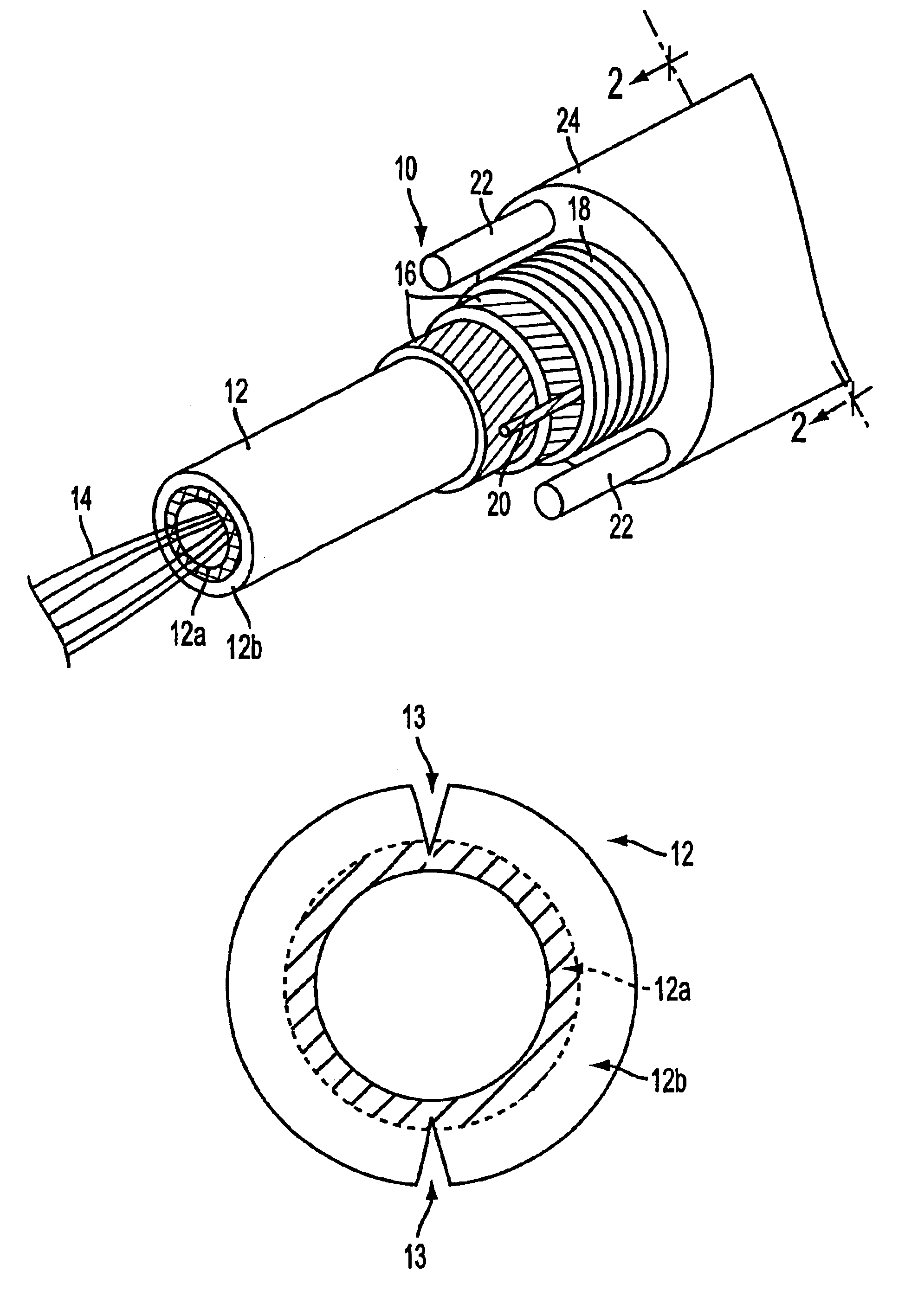
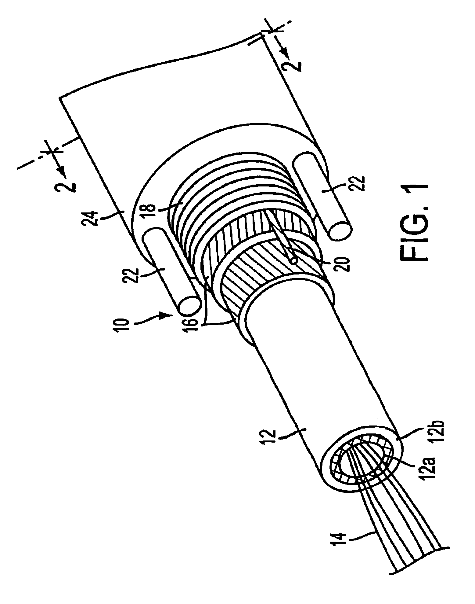
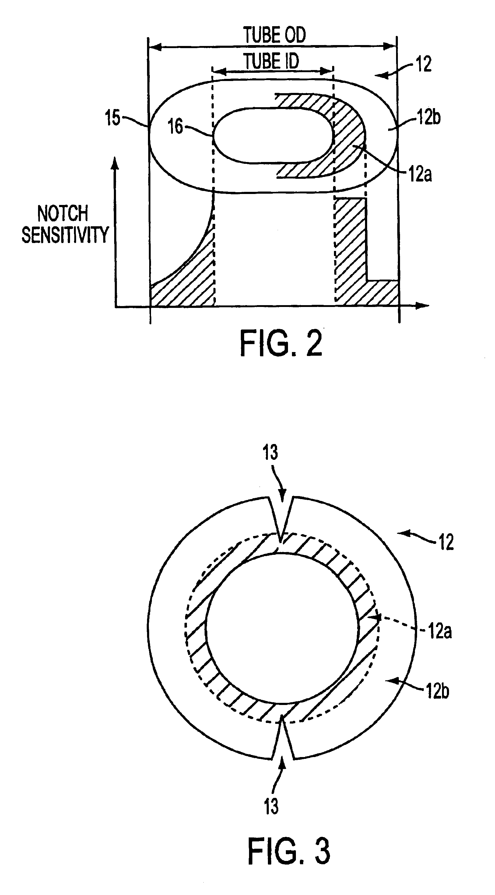
The present invention is about a new design for buffer tubes used in fiber optic cables. The new design offers a way to access the optical fibers inside the buffer tube without damaging them. The buffer tube is made up of two layers - an inner layer and an outer layer. The inner layer is more sensitive to notch-based cuts and is designed to allow for easy access to the optical fibers. The outer layer provides most of the strength and protection for the cable. The new design also allows for efficient mid-span access to the optical fibers without damaging them. The invention offers a better way to access and protect the optical fibers in fiber optic cables.

Problems solved by technology

Too much shrinkage or expansion of the buffer tube caused by temperature changes could place tensile or compressive loads on the optical fibers residing therein.
High tensile or compressive loads can result in damaged or broken optical fibers.
Known buffer tube designs, either single- or multi-layer, have an additional disadvantage in the difficulty of accessing the optical fibers mid-span.
This problem is exacerbated by the recent tendency in optical fiber design to pack greater numbers of optical fibers into smaller buffer tubes.
As the fiber density inside tubes increases, free space inside the tubes decreases, and it is more likely to damage optical fibers when a buffer tube is opened with a cutting tool.
However, this procedure may be difficult, because buffer tube materials typically do not break readily in order to meet the design constraints discussed above.

Method used


Image

  • Buffer tube design for easy and reliable access in mid-span
  • Buffer tube design for easy and reliable access in mid-span
  • Buffer tube design for easy and reliable access in mid-span

Examples


Embodiment Construction

The present invention, according to the first embodiment, contemplates a buffer tube with a dual layer buffer tube wall. The inner layer, which is closest to the optical fibers, is more notch-sensitive than the outer layer. It is intended that a cut be made through the entire outer layer, but only partially into the inner layer. Because of its relatively high notch-sensitivity, the cut in the inner layer easily propagates through the inner layer so that the optical fiber contents of the buffer tube are easily exposed. The outer buffer tube layer surrounds the outside of the inner buffer tube layer and provides much of the structural and barrier properties typically required by buffer tube walls.

In a preferred embodiment, dual layer extrusion is used to manufacture a dual layer buffer tube having inner and outer layers. The outer layer may be a material conventionally used for buffer tube walls, such as polybutylene terephtalate. The inner layer may be made from a material having a r...


PUM


Abstract

The present invention is directed to a novel construction of buffer tubes for fiber optic cables which offers a way to access the optical fibers inside a buffer tube while reducing the risk of damaging the fibers, as sometimes occurs when cutting the outer layer of the buffer tube. A buffer tube for use in a fiber optic cable of the present invention comprises a tube having a tube wall, the wall having an inside and outside surface, wherein an inner portion of tube wall, nearest the inside surface, is made of a material having a higher notch-sensitivity than an outer portion of the tube wall nearest the outside surface.

Description

The present invention relates generally to the field of fiber optic cables. In particular, the present invention is directed to a novel construction of buffer tubes for fiber optic cables which offers a way to access the optical fibers inside a buffer tube while reducing the risk of damaging the fibers, as sometimes occurs when cutting the outer layer of the buffer tube.DISCUSSION OF RELATED ARTOptical fiber cables have been used for many years to transmit information at high rates and very long distances. The transmission medium of the optical fiber cable are delicate optical fibers. Ordinarily, these optical fibers reside in a buffer tube or in a core tube. Hereinafter, for the sake of simplicity, buffer tubes shall also include core tubes. The buffer tube protects the optical fibers residing therein. The buffer tube may be fabricated from a single material or from a combination of two or more materials.In many fiber optic cable designs, it is desirable to have a buffer tube made ...

Claims


Application Information

Patent Timeline
Patent Type & Authority Patents(United States)
IPC IPC(8): G02B6/44
CPCG02B6/4495G02B6/443G02B6/4431
Inventor WITT, GEOFFRISCH, BRIAN
Owner ALCATEL LUCENT SAS
Learn More