Sheet metal stud and composite construction panel and method

a technology of composite construction and metal studs, which is applied in the direction of building components, structural elements, roof coverings, etc., can solve the problems of large heat loss through the panels, large labor costs, and large weight of concrete panels, and achieve the effect of reducing labor costs, reducing labor costs, and reducing construction costs

Inactive Publication Date: 2004-03-23
GCG HLDG
View PDF18 Cites 117 Cited by
  • Summary
  • Abstract
  • Description
  • Claims
  • Application Information

AI Technical Summary

Problems solved by technology

Concrete panels are usually of relatively heavy thick material of great weight.
Great costs are involved in both materials, labor transportation, and erection of such heavy panels.
However it is known that the metal studs conduct heat from the building interior to the concrete panels and there are thus substantial heat losses through the panels due to such metal studs.
It is not possible to the builder to cut away any of the diagonal struts to provide larger openings for services, since this would drastically reduce the strength of the studs.
Another problem arose in that the triangular openings were formed with edge flanges around their perimeter.
However where these edge flanges extended around an angular corner of the generally triangular or trapezoidal shaped opening there was a tendency for the sheet metal in the edge flange to crack.
This meant that there was more metal at each of the corners, than was desirable for heat transfer, and thermal losses could occur.
Also at these angular corners it was found that it was not possible to bend or form the edge flanges of the struts in the studs into a full right angle bend.
However this solution was not totally satisfactory since, by reducing the angle of the edge flange, the strength of the overall stud was also reduced.
Another problem arose in cutting these studs to length.
However due to the alternating orientation of the openings there were problems in cutting off the studs to a specific length.
This was waste metal and increased the cost of the building.
This was not thought to be possible since circular openings, or openings with long radius corners, or semi-circular corners would leave excessive metal in the stud which would still cause heat transfer losses.
Finally, cutting to length of a stud with identical circular openings may result in much less wastage of material and this is another cost saving.

Method used


Image

  • Sheet metal stud and composite construction panel and method
  • Sheet metal stud and composite construction panel and method
  • Sheet metal stud and composite construction panel and method

Examples


Embodiment Construction

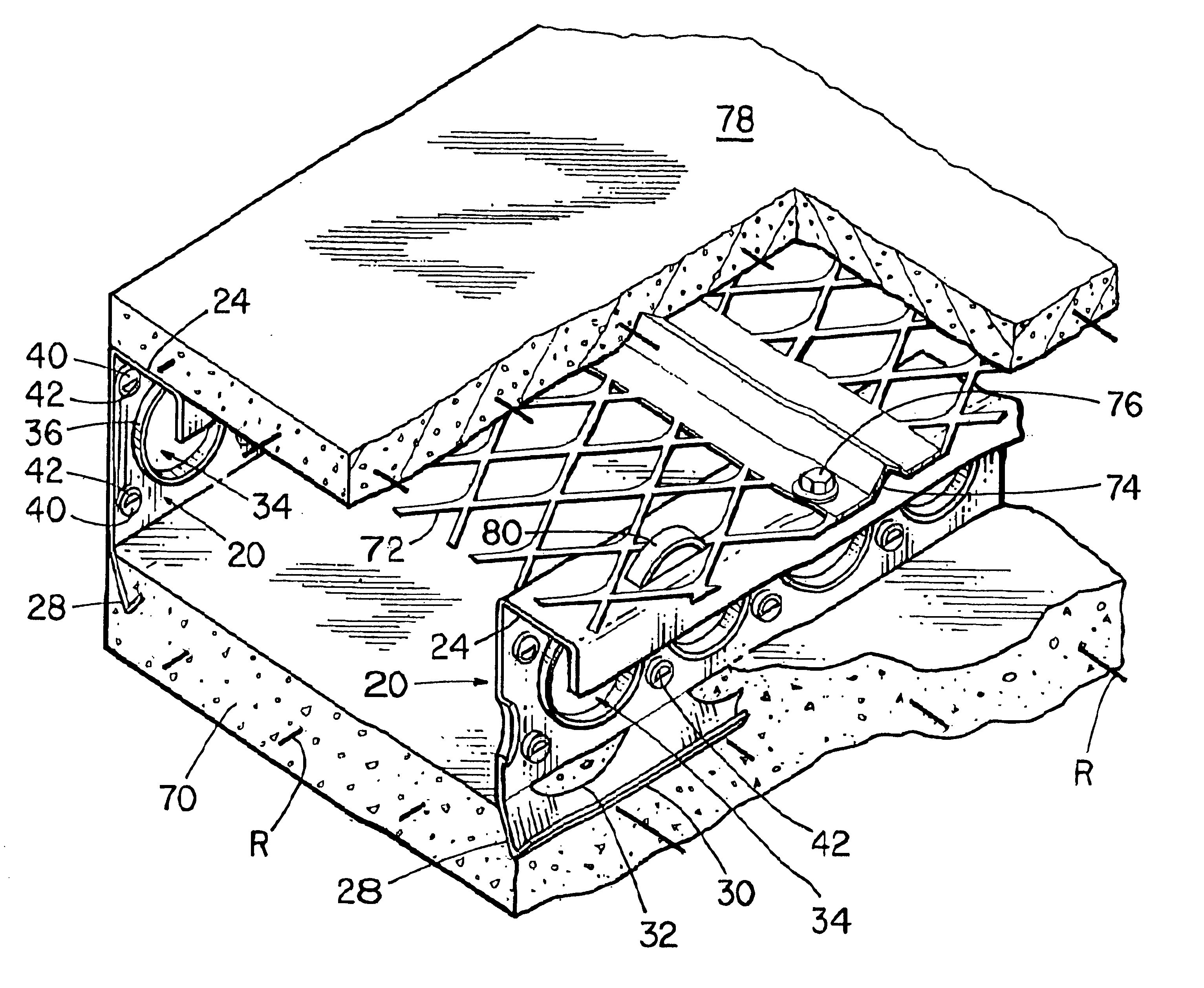
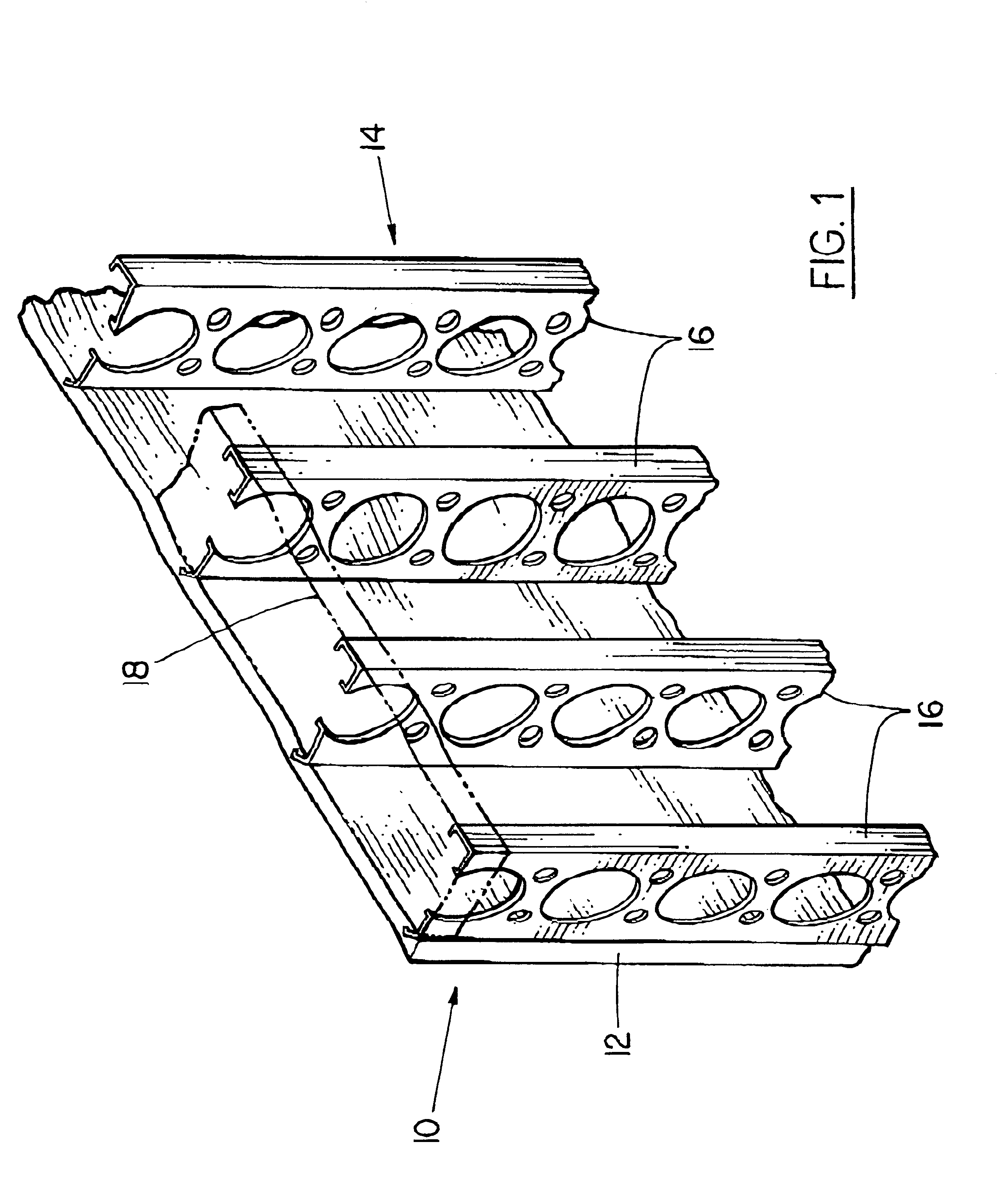
Referring first of all to FIG. 1 it will be understood that the invention relates generally to a composite wall panel 10 typically looking somewhat like the illustration of FIG. 1. Such a composite panel 10 has a thin panel 12 of cast material, and a reinforcing frame or grid indicated generally as 14, formed of sheet metal studs indicated generally as 16. Typically the cast material is concrete, but various special forms of concrete are available, which would be suitable for the purpose. However the invention is not limited to concrete materials as such, but includes other panel materials which are capable of being cast into a thin panel and allowed to cure. As will be explained below such studs have embedment portions which are embedded into the concrete 12.

Typically the studs 16 may be arranged on twenty-four inch centers, and may have top and bottom transverse studs 18 joining the top and bottom ends of the studs 16. The top and bottom studs will usually be plain C-section studs...


PUM


Abstract

A composite construction panel having a thin panel of concrete material and a reinforcing grid of sheet metal studs with embedment portions which are actually embedded into the concrete panel, each of the studs having a web, main web openings through the web, a right angular flange formed on a free edge of the web, an embedment angled flange portion formed along the opposite edge of the web, an edge strip formed on the angled flange at an angle thereto; and, spaced apart angled flange openings formed in the angled flange for flow of concrete therethrough. An alternate form of stud has a triangular tube structure along one edge of the web. Another form of stud has a discontinuous webs defining spaces between them. In one embodiment two concrete panels may be secured to the studs in spaced relation to create a hollow structure.

Description

The invention relates to a sheet metal stud, and in particular to a sheet metal stud adapted to be partially embedded in a thin wall panel of cast material, such as concrete, for reinforcement of such a panel, and to a composite thin wall panel of cast material, such as concrete, having reinforcing studs partially embedded in said panel, and to a method of forming a composite panel.PRIOR ARTSteel studs of a wide variety have been proposed for erecting structures. Usually such studs are used to replace wooden studs. Concrete panels are also in wide use for attachment to the exterior of a structure to provide for a wide variety of functional and aesthetic effects. Concrete panels are usually of relatively heavy thick material of great weight. Great costs are involved in both materials, labor transportation, and erection of such heavy panels. Proposals have been made for using panels of reduced thickness. Such thin wall panels are reinforced by a framework of metal studs. Usually edges...

Claims


Application Information

Patent Timeline
Patent Type & Authority Patents(United States)
IPC IPC(8): E04C3/08E04C2/38E04C3/04
CPCE04C2/384E04C3/083E04C2003/0421E04C2003/0434E04C2003/0439Y10T428/12368E04C2003/046E04C2003/0473Y10T428/12354Y10T428/1241E04C2003/0452
Inventor BODNAR, ERNEST R.
Owner GCG HLDG
Why Eureka
Try Eureka