

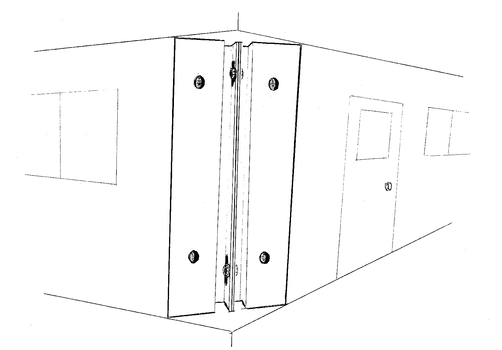
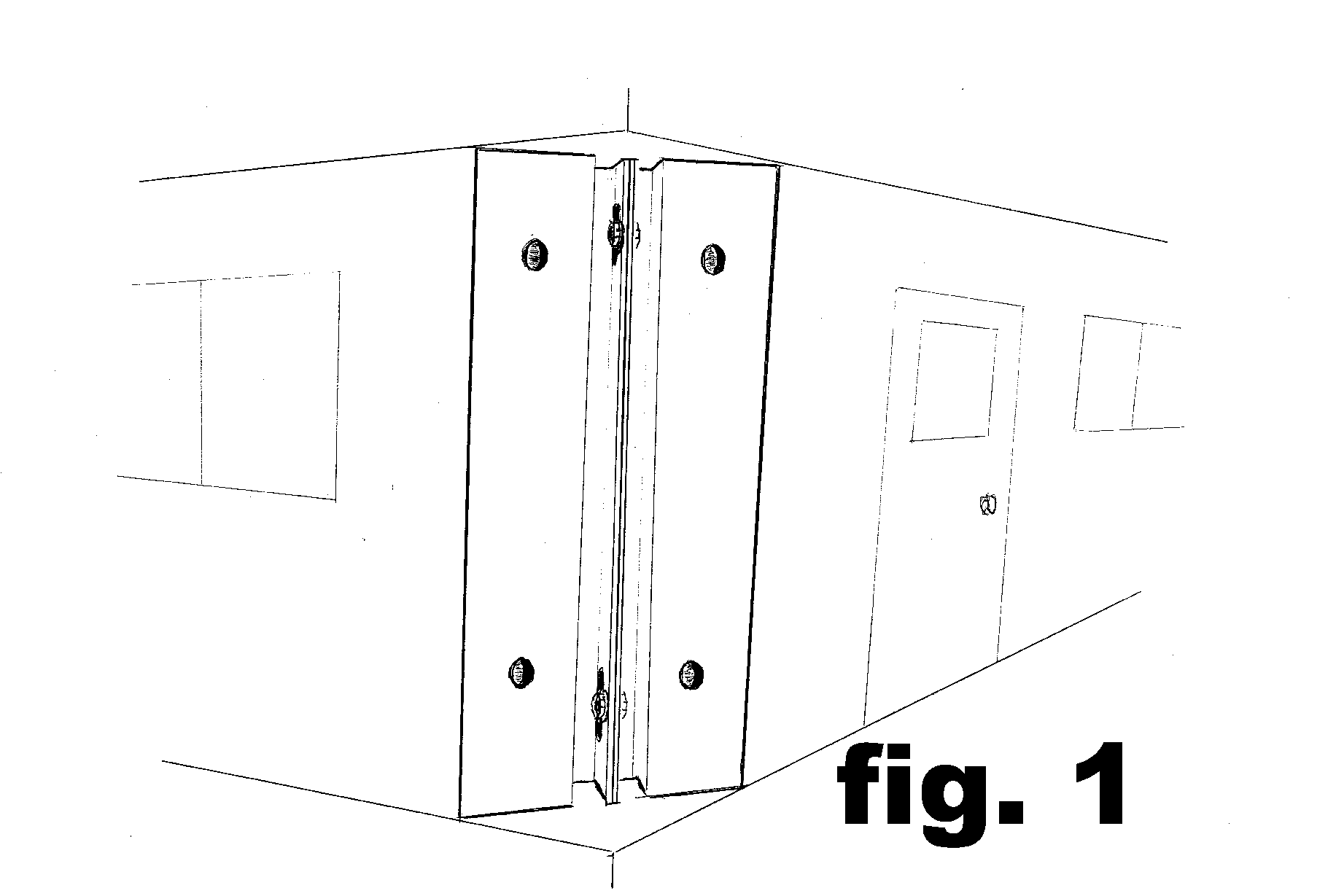
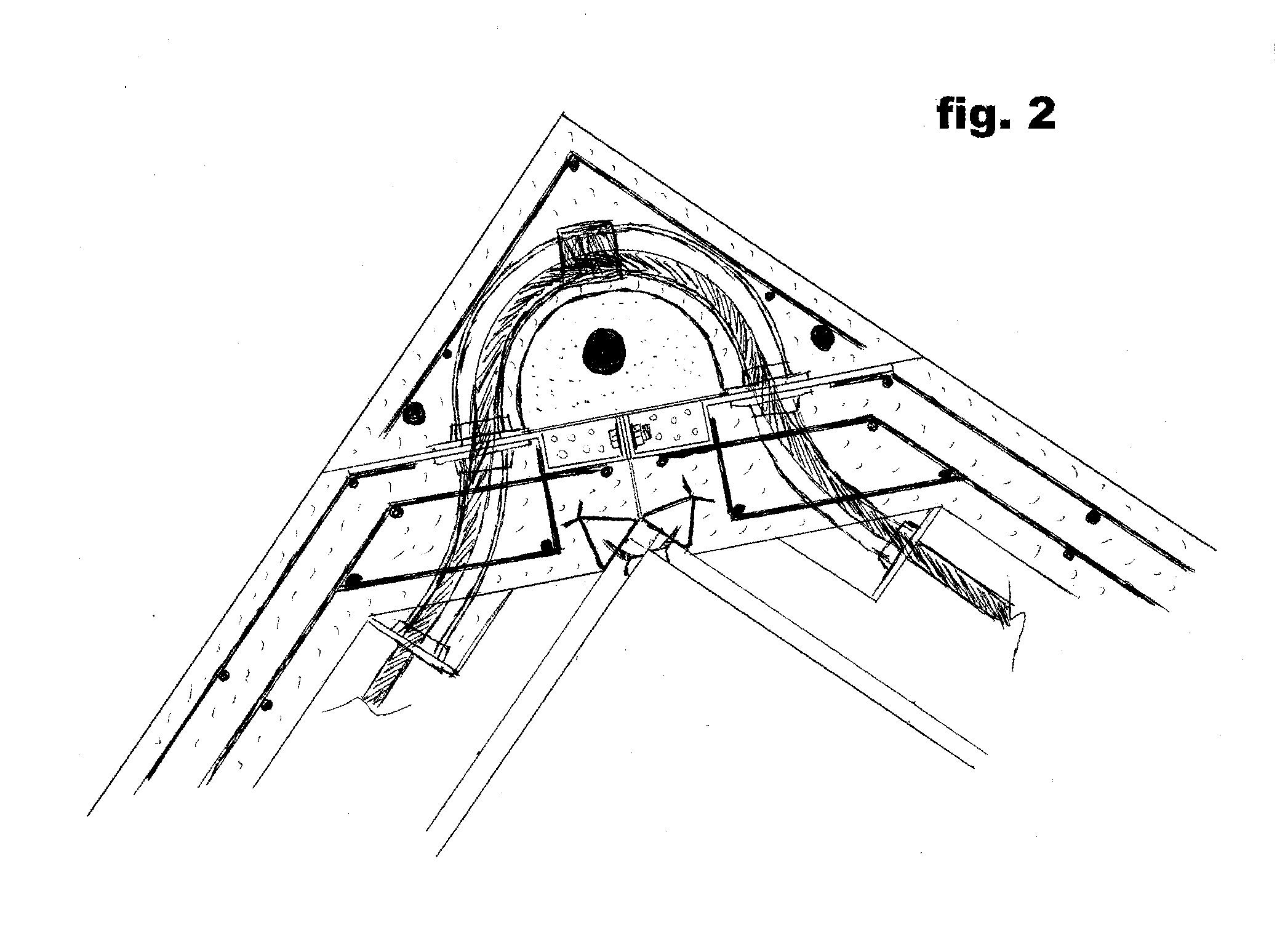
Connectors and Methods of Construction for a Precast Special Concrete Moment Resisting Shear Wall and Precast Special Concrete Moment Resisting Frame Building Panel System
a technology of special concrete and connection method, which is applied in the direction of walls, surface layering apparatus, manufacturing tools, etc., can solve the problems of plastic hinge region, lack of ductile connection of beams, shear walls or columns within the building, and the difficulty of conventional methods of constructing prefabricated concrete buildings and particularly prefabricated concrete foundations in seismically active areas
- Summary
- Abstract
- Description
- Claims
- Application Information
AI Technical Summary
Benefits of technology
Problems solved by technology
Method used
Image

Examples
Embodiment Construction
[0064]Conventional architectural building plans are prepared for a prospective building owner or developer by an architect or engineer. Soil, geo-technical, civil, and any other engineering studies required by the code and local building officials are prepared. The plans are submitted to a licensed panel manufacturer for evaluation of engineering requirements by an authorized engineer.
[0065]A feasibility study is performed and upon acceptance an estimate of the building and construction costs is prepared. When a contract to build is executed, the licensed panel manufacturer prepares the necessary plans and documentation for permit application, including engineering of the structural assembly components, structural walls, columns, beams, diaphragms, moment frames, trusses, reinforcement bar, wire, cable, anchors, inserts, plates, ductile connectors, channel, tubing, and any other embedded elements and any other structural members.
[0066]Engineering documentation of all loads, shear, s...
PUM
| Property | Measurement | Unit |
|---|---|---|
| Angle | aaaaa | aaaaa |
| Flexibility | aaaaa | aaaaa |
| Tension | aaaaa | aaaaa |
Abstract
Description
Claims
Application Information