Catheter with composite construction

a composite construction and catheter technology, applied in the field of electrophysiologic catheters, can solve the problems of reducing the accuracy of the position sensing capabilities of the sensor, limiting the flexibility and deflection of the distal tip section, and forming a lesion within the cardiac tissue which is electrically non-conductive, so as to achieve less space, increase the size of the catheter, and improve the effect of us

Active Publication Date: 2013-09-26
BIOSENSE WEBSTER (ISRAEL) LTD
View PDF2 Cites 47 Cited by
  • Summary
  • Abstract
  • Description
  • Claims
  • Application Information

AI Technical Summary

Benefits of technology

[0015]The present invention is directed to a catheter having a composite and segmented construction in a distal section that allows space in the distal section to be used efficiently without the need to increase catheter size. The distal section includes at least one deflectable member and at least one support member arranged in alternating sequence, with the support member being sufficiently rigid to support and carry a ring electrode and the deflectable member being more flexible than the support member to allow deflection of the distal section as a whole. Also carried on the supp...

Problems solved by technology

The tissue is heated sufficiently to cause cellular destruction in the cardiac tissue resulting in formation of a lesion within the cardiac tissue which is electrically non-conductive.
Because of the size of the tip electrode and the limited interior space therein, the EM sensor is often positioned outside of the tip electrode, proximally thereof, and often off-axis from the tip electrode which can reduce the accuracy of the position sensing capabilities of the sensor.
Being outside the tip electrode, the position sensor is also exposed to bending stresses and can limit the flexibility and def...

Method used


Image

  • Catheter with composite construction
  • Catheter with composite construction
  • Catheter with composite construction

Examples


Embodiment Construction

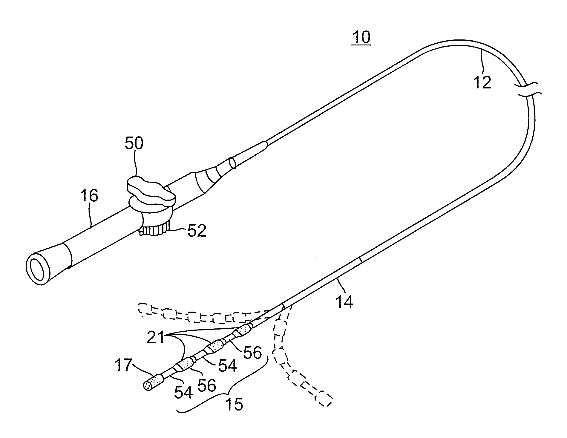
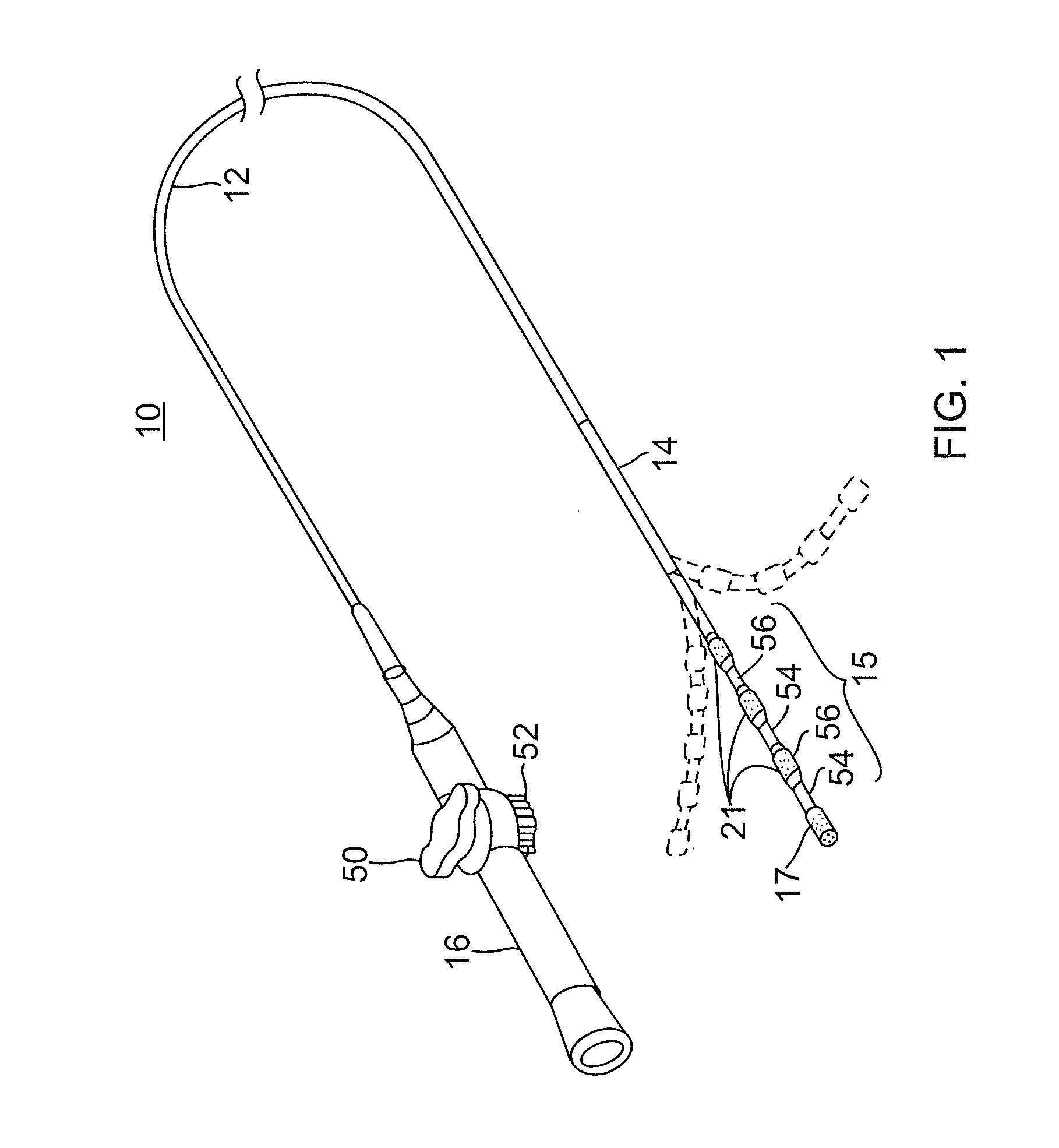
[0035]FIG. 1 illustrates an embodiment of a catheter 10 carrying irrigated tip and ring electrodes with location sensing and cooling capabilities. The catheter has an elongated catheter body 12 with proximal and distal ends, an intermediate deflectable section 14 at the distal end of the catheter body 12, and a distal section 15 with an irrigated tip electrode 17 and a plurality of irrigated ring electrodes 21. The catheter also includes a control handle 16 at the proximal end of the catheter body 12 for controlling deflection of the intermediate section 14. Advantageously, the distal section 15 has a composite and segmented construction comprising alternating segments of deflectable lumen members 54 and ring electrode support members 56. The construction facilitates the efficient use of space in the distal section 15 as the construction allows all the lumens in the distal section to be used for components other than position sensing coils which otherwise tend to require dedicated a...


PUM


Abstract

A catheter has a composite and segmented construction in a distal section that includes deflectable members and support member arranged in alternating sequence, with each support member carrying a ring electrode and the deflectable members being flexible to allow deflection of the distal section as a whole. Carried on an outer surface of the support member is a coil location sensor. The distal section is configured with a distal irrigation fluid path extending axially through the deflectable members and the support members to deliver irrigation fluid to the ring electrode and the tip electrode. A method of constructing a catheter includes building a section of the catheter from the inside out by mounting the support members on a tubing at predetermined locations and filling gaps in between with a more flexible material to form the deflectable members by extrusion segments or injection molding over assembled components internal to the catheter.

Description

FIELD OF INVENTION[0001]The present invention relates to an electrophysiologic catheter that is particularly useful for ablation and sensing electrical activity of heart tissue.BACKGROUND OF INVENTION[0002]Electrode catheters have been in common use in medical practice for many years. Diagnosis and treatment of cardiac arrythmias by means of electrode catheters include mapping the electrical properties of heart tissue and selectively ablating cardiac tissue by application of energy. Such ablation can cease or modify the propagation of unwanted electrical signals from one portion of the heart to another. The ablation process destroys the unwanted electrical pathways by formation of non-conducting lesions. Various energy delivery modalities have been disclosed for forming lesions, and include use of microwave, laser and more commonly, radiofrequency energies to create conduction blocks along the cardiac tissue wall.[0003]In a two-step procedure—mapping followed by ablation—electrical ...

Claims


Application Information

Patent Timeline
IPC IPC(8): A61B18/14
CPCA61B18/1492A61B2218/002A61B2017/00053A61B2017/00243A61B2017/00314A61B2017/00323A61B2017/00526A61B2018/00029A61B2018/00065A61B2018/00166A61B2018/00577A61B2018/0097A61B2018/1467A61B2019/5251A61B2217/007A61B2018/00357A61B2018/00821A61B2018/00839A61B19/5244A61B34/20A61B2034/2051A61B2018/00178A61B2018/00351
Inventor SCHULTZ, JEFFREY W.
Owner BIOSENSE WEBSTER (ISRAEL) LTD
Why Eureka
Try Eureka