

Methods and apparatus for recycling cryogenic liquid or gas from test chambers
a cryogenic liquid and test chamber technology, applied in the field of methods and apparatus for recycling cryogenic liquid or gas from test chambers, can solve the problems of environmental stress on manufactured products, add a significant cost to the manufacturing process of end products,
- Summary
- Abstract
- Description
- Claims
- Application Information
AI Technical Summary
Benefits of technology
Problems solved by technology
Method used
Image

Examples
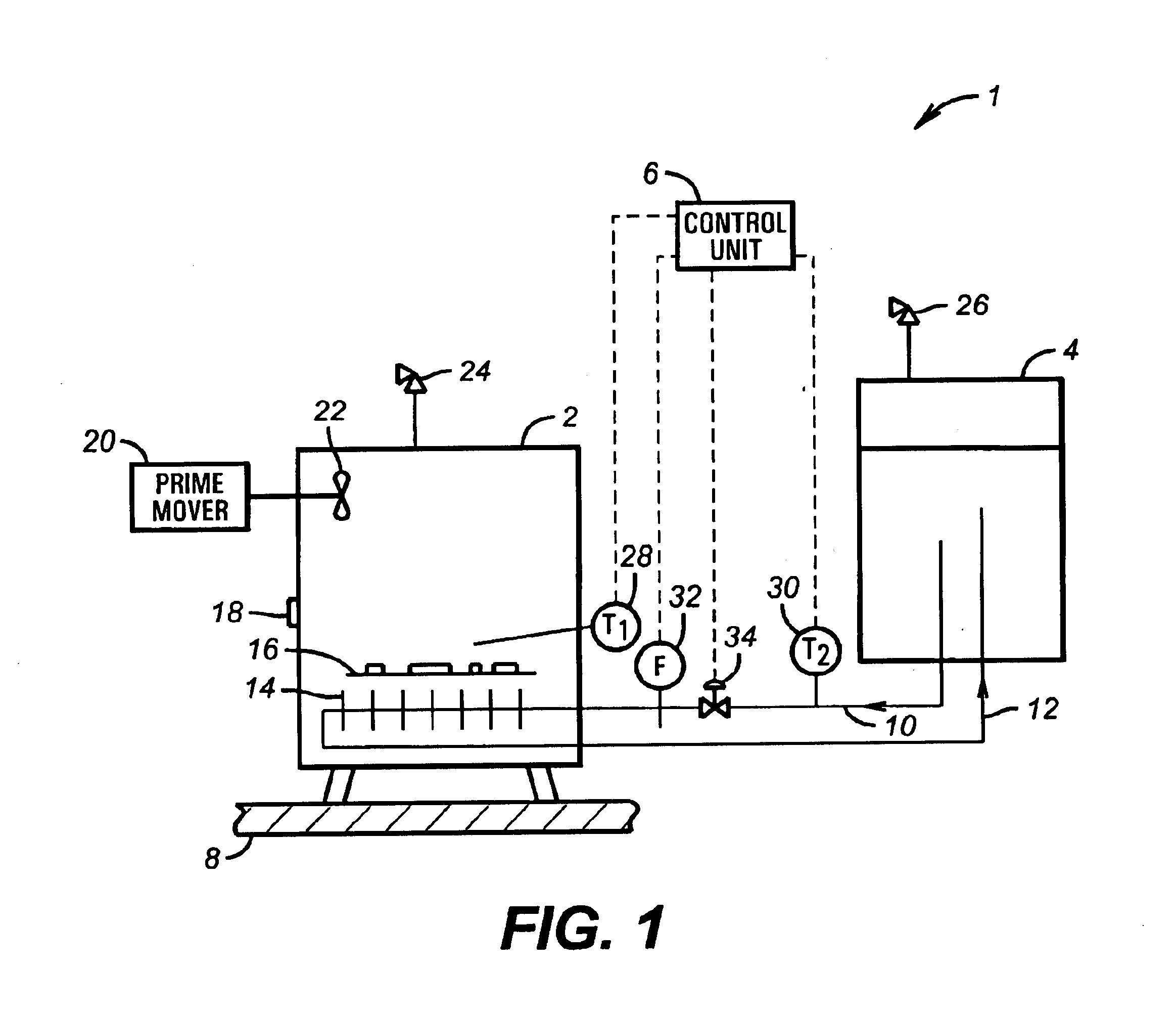
embodiment 50
Cryogenic fluid source 54 feeds a conduit 82 and flow regulator 84 with cryogenic fluid. Conduit 82 typically splits into one or more conduits, illustrated in FIG. 2 as 81 and 83, which feed coils 80 and 78, respectively. Coils 80 and 78 are "smartly positioned" in environmental stress screening chamber 52 so as to provide optimal cooling of component 16. For example, as illustrated in embodiment 50 in FIG. 2, coils 78 and 80 may be positioned directly below and above component 16. A block valve 85 preferably allows gas to bypass chamber 52, if open. This may be preferred for example, if more inert gas is desired in other areas of the plant.
After being compressed by compressor 62, if desired, a pressure regulator 90 may allow high pressure cryogenic gas to flow out of high pressure storage unit 58, through conduit 93, back pressure regulator 90, and check valve 92 into conduit 96. Conduit 96 then routes high-pressure cryogenic gas to other end users within the same or other plants. ...
embodiment 200
Another preferred embodiment 200 of the invention is illustrated in FIG. 3. Embodiment 200 includes a test cabinet 202 in which is placed a component to be tested 204, indicated here as a radar sub-system. Sub-system 204 rests on a shelf 206, which in turn rests or is connected to a support 208 through which devices such as sub-system 204 are preferably electrically connected to a power source (not shown). In this way, devices 204 are preferably powered up and operated in simulated environments. Test cabinet 202 rests on a plant floor 210 or other support surface. Embodiment 200 includes a gas plenum 212 through which vaporized cryogen flows, as indicated by the various arrows 216. The gas flows through plenum 212 and then through nozzles 214 (six depicted in FIG. 3, although this number may vary). Nozzles 214 direct gas toward and around sub-system 204 to achieve temperature change of the test component. Fans 218 and 220 in this embodiment are disposed near the top of cabinet 202, ...
PUM
| Property | Measurement | Unit |
|---|---|---|
| temperature | aaaaa | aaaaa |
| temperature | aaaaa | aaaaa |
| pressure | aaaaa | aaaaa |
Abstract
Description
Claims
Application Information