Hydraulic valve

Inactive Publication Date: 2004-03-30
BRANDELLI ANTHONY
View PDF20 Cites 30 Cited by
  • Summary
  • Abstract
  • Description
  • Claims
  • Application Information

AI Technical Summary

Problems solved by technology

Consequently, even very tiny particulates of sediment, sand, scum, or dirt can cause a blockage within the valve orifices, central passage, or bleed apertures through the wall of the core.
The valve will thereafter operate improperly until repaired or replaced.
Clogging of the valve passage is particularly likely since at least a portion of the passage through the core is open to fluid when the metering pin is reciprocated to unseat the body of the valve from the valve seat.
At this point in the operation of the valve there is a considerable onrush of water directed straight up into the passage.
Another problem that has persisted in the operation of conventional ballcock valves is the rather lengthy fill time and noisy operation of the valve, particularly as it approaches a closed condition.
This problem occurs due to the inordinately long lever arm that is utilized to manipulate the metering pin.
As a consequence, the rate at which pressure builds up in the back-pressure chamber rises progressively, but very slowly, thus lengthening the time required for sufficient pressure to build up in the back-pressure chamber to seat the body of the diaphragm against the valve seat.
During this time there is an annoying hissing noise due to the slow passage of water past the metering pin and through the upper sealing ring.
While the foregoin

Method used


Image

  • Hydraulic valve
  • Hydraulic valve
  • Hydraulic valve

Examples


Embodiment Construction

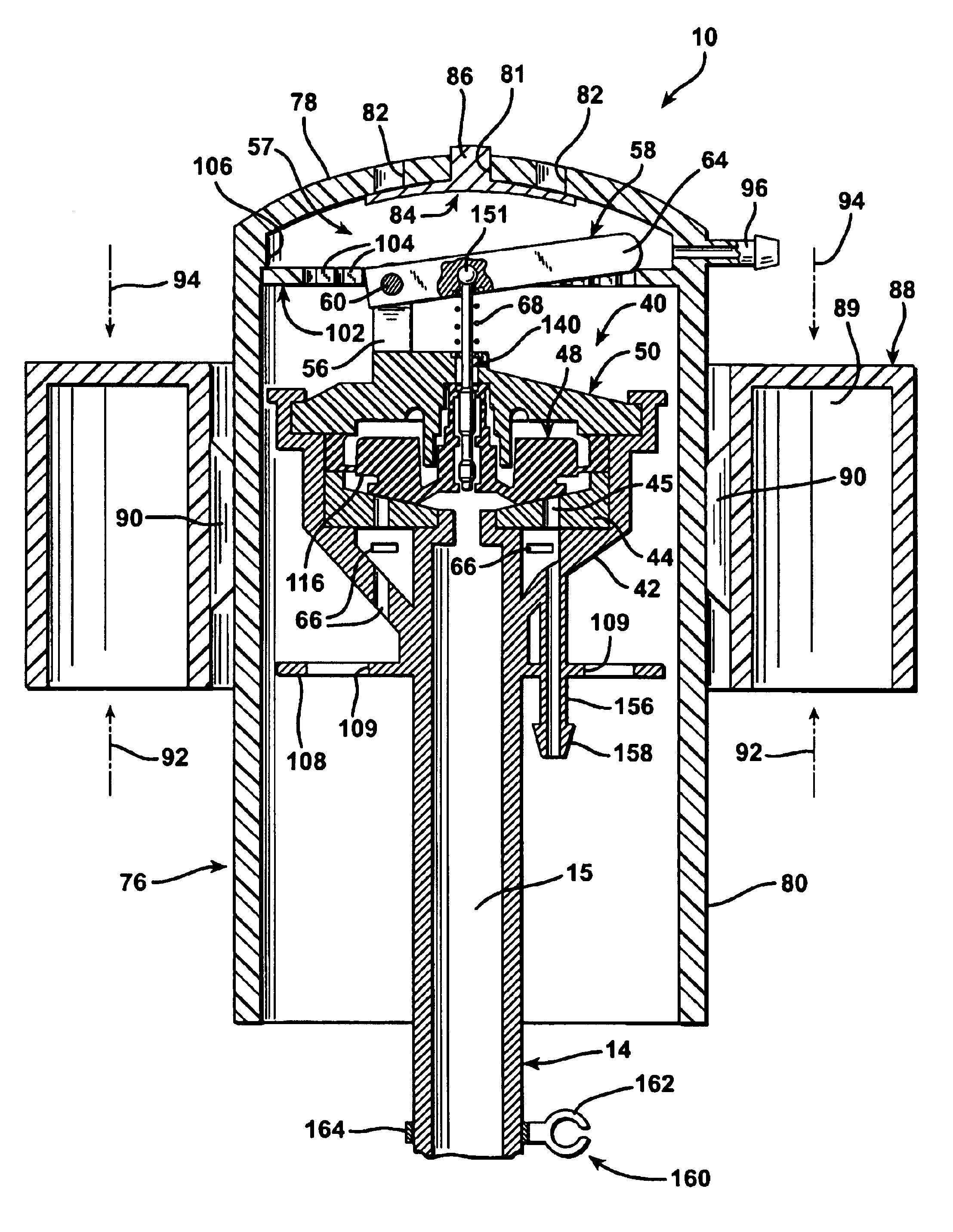
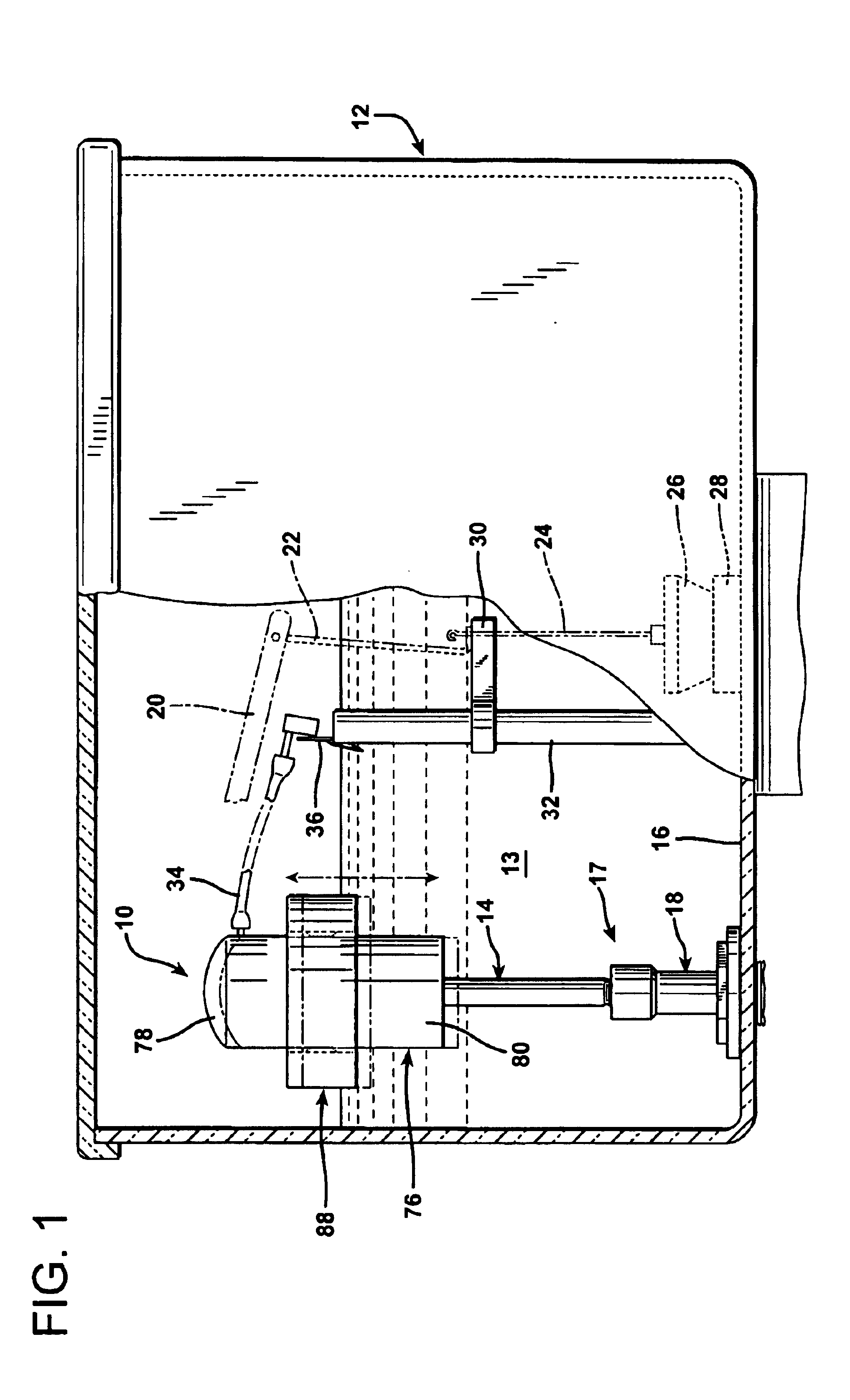
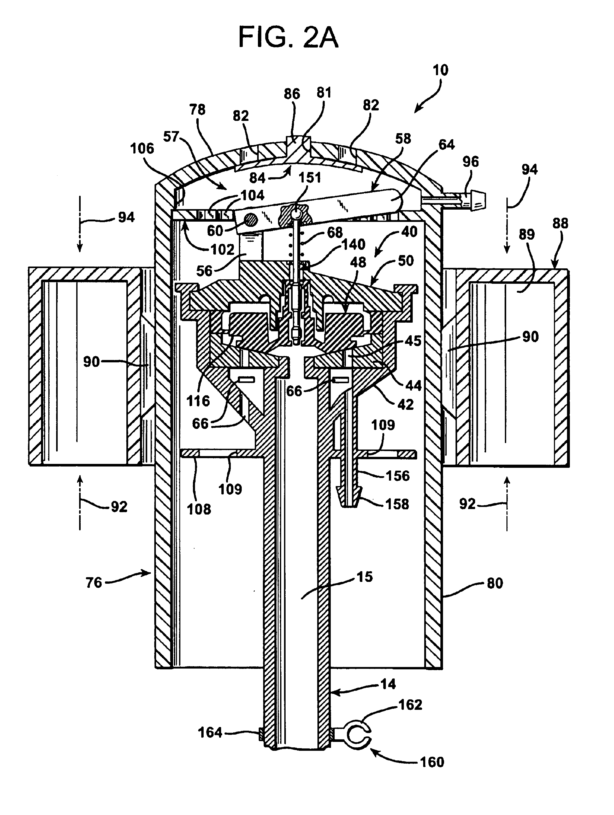
FIG. 1 illustrates a ballcock valve assembly 10 according to the invention located in the conventional flush tank 12 of a toilet water closet. The tank 12 is normally filled with water 13, to a maximum level 100, as illustrated. The ballcock valve assembly 10 is mounted atop an upright fluid supply pipe 14 that is secured to the bottom 16 of the tank 12 by means of a mounting coupling 17, hereinafter to be described.

The remaining components of the flush tank 12 are of a conventional design and include a flushing arm 20 actuated by a conventional flush lever (not shown) to raise lift wires 22 and 24 to unseat a stopper 26 from a flush valve seat 28 that in turn leads to a toilet bowl (not shown). The lower lift wire 24 is guided through an opening in a horizontally projecting guide wire bracket 30 that is secured to a hollow, vertical overflow pipe 32 that also leads to the toilet. Alternatively, a chain 23 may be connected from the flushing arm 20 directly to the movable end of a fl...


PUM


Abstract

A fluid tank valve assembly of the type employed for water tanks for toilets has a tank refill valve located atop a fluid inlet supply tube. The refill valve has a lever that is raised and lowered to open and close the valve. An inverted, cup-shaped hood is positioned atop the valve and a float is located about the skirt of the hood and secured thereto by the force of friction. The float can be moved longitudinally along the skirt of the hood in order to vary the water level at which the hood bears down upon the lever arm or is lifted from the lever arm, thereby varying the water level at which the valve is actuated. The valve itself is equipped with a metering pin that is configured to reduce the likelihood of clogging in the longitudinal passage of the core of the valve diaphragm. A unique coupling between the water inlet supply tube and the hollow mount at the bottom of the tank prevents complete separation of the water inlet supply tube relative to the mount, but permits longitudinal adjustment therebetween so as to vary the height at which the refill valve is mounted within the tank.

Description

1. Field of the InventionThe present invention relates to a fluid tank valve, particularly a hydraulic refill valve, especially adapted for use in controlling the level of a liquid within a tank.2. Description of the Prior ArtHydraulic valves have been used for many years for controlling the level of a liquid within a tank. Such valves are widely utilized in the plumbing industry, particularly in regulating the flow of water into the tank of a toilet, sometimes termed a water closet. Conventional valves of this type, often called ballcock valves, are described, for example, in U.S. Pat. Nos. 3,429,333 and 4,100,928.While some changes have been made in the construction of ballcock valves throughout the years, the operating mechanisms of conventional, commercially available ballcock valves sold for use in toilets have remained largely standardized for many years. For example, ballcock valves similar to the type described in U.S. Pat. No. 4,100,928 are widely sold throughout the United...

Claims


Application Information

Patent Timeline
IPC IPC(8): E03D1/30E03D1/32F16K21/00F16K21/18
CPCE03D1/32F16K21/18Y10T137/7361Y10T137/7374Y10T137/7413Y10T137/7426Y10T137/7433Y10T137/7446Y10T137/7449Y10T137/7462Y10T137/7472
Inventor BRANDELLI, ANTHONY
Owner BRANDELLI ANTHONY
Why Eureka
Try Eureka