
Conveyorized oven with automated door

a technology of automatic door and oven, which is applied in the field of ovens, can solve the problems of presenting problems which are much more complex, and the intensity of microwave energy permitted to leak from domestic and/or industrial microwave heating systems is restricted, so as to reduce the number of operators for each oven, reduce the amount of heat and/or microwave loss, and increase the efficiency of the oven

Inactive Publication Date: 2004-03-30
ACP OF DELAWARE
View PDF10 Cites 58 Cited by
  • Summary
  • Abstract
  • Description
  • Claims
  • Application Information

AI Technical Summary

Benefits of technology

"The present invention is an oven for heating food items that has a plurality of oven cavity walls, an oven heat source, an entrance door, an exit door, a conveyor belt, and a programmable logic center. The oven allows for the transport of food items into and out of the oven cavity through the doors, and the movement of the conveyor belt and motor controls the movement of the doors. The programmable logic center controls the movement of the doors, preventing the oven heat source from heating the food item when the doors are open. The oven also has interlocking doors that move simultaneously, and sensors and a programmable logic center to control the movement of the doors. The technical effects of the invention include improved heating efficiency, improved food item transport, and improved safety."

Problems solved by technology

In fact, the intensity of microwave energy permitted to leak from domestic and / or industrial microwave heating systems is restricted.
The suppression of microwave energy and heat loss from these continuous access openings has presented problems which are much more complex than a batch-type microwave oven or convection oven that do not include a conveyor belt and that can be manually sealed using a door.

Method used


Image

  • Conveyorized oven with automated door
  • Conveyorized oven with automated door
  • Conveyorized oven with automated door

Examples


Embodiment Construction

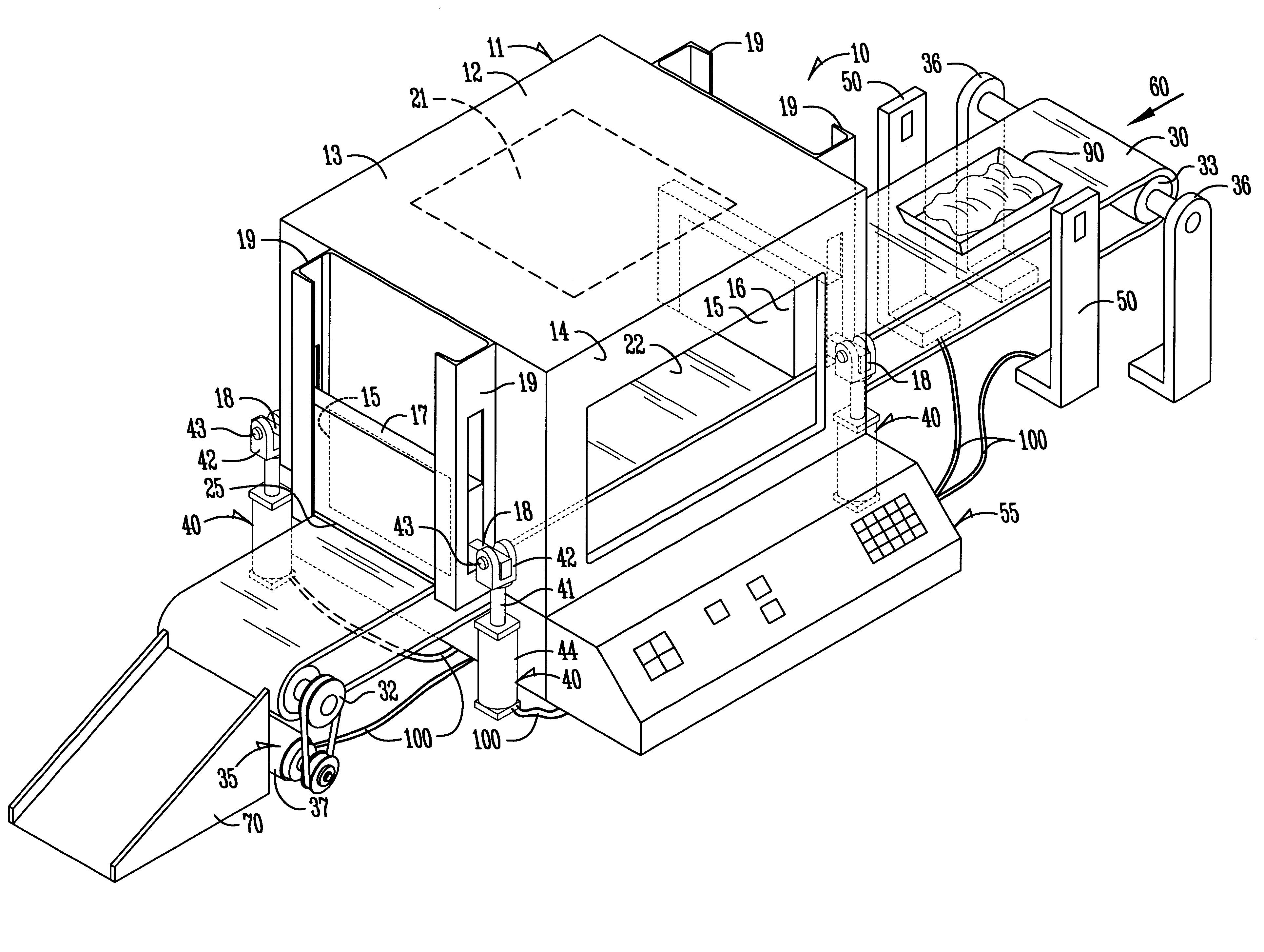
The invention is directed to ovens, and in particular, microwave ovens having a conveyor belt for passing items through the microwave oven. "Items" is herein defined as any object, industrial or otherwise, that is desired by the operator of the oven to be heated. Example items include, but are not limited to, food items, rubber items, and foundry cores. While the following description of several specific embodiments are directed to microwave ovens, it is to be understood that the present invention is also directed to conventional ovens, e.g., convection ovens.

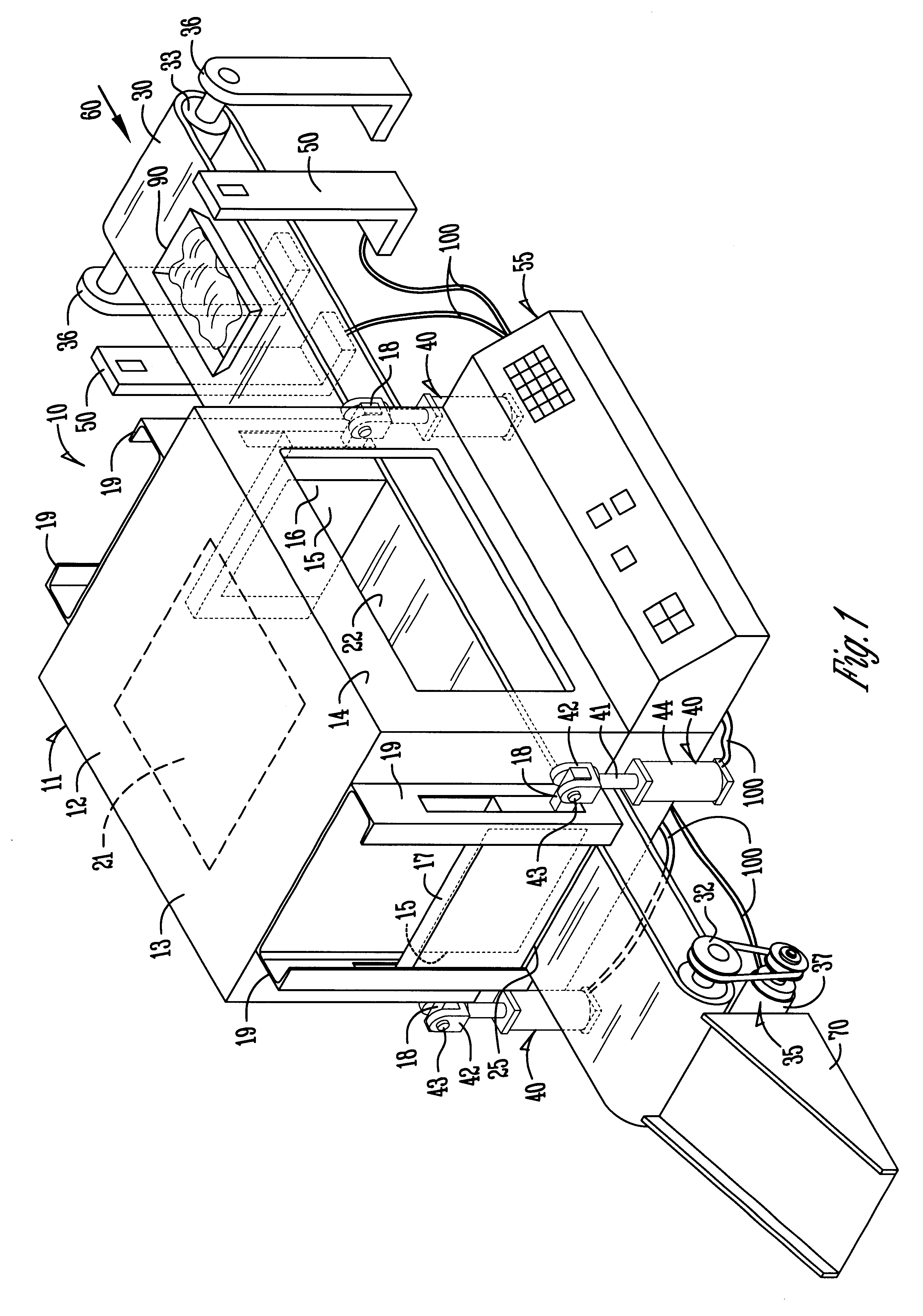
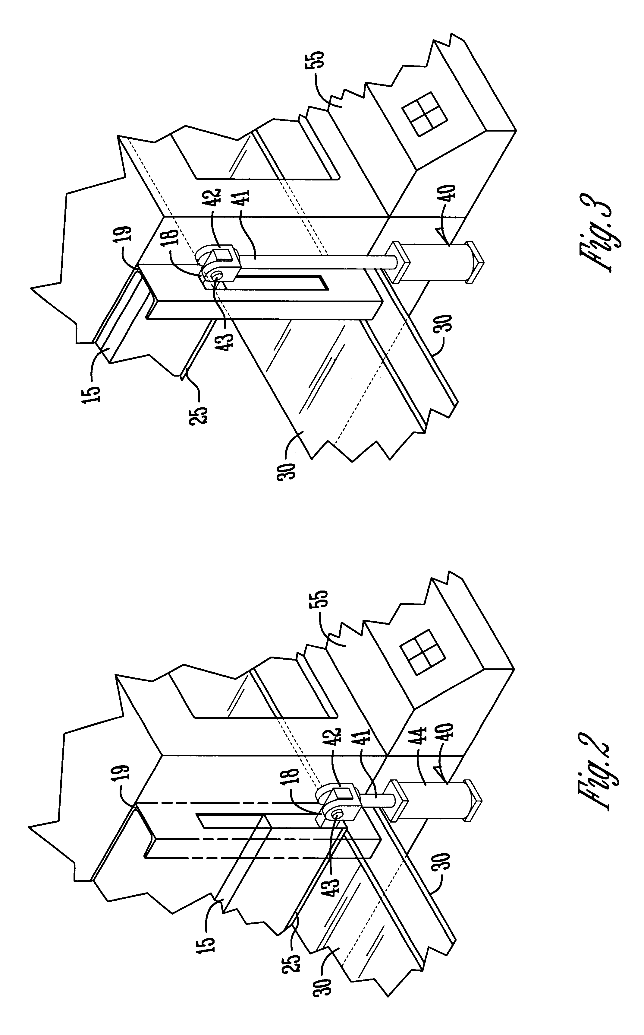
Referring now to FIGS. 1-5, in one specific embodiment of the present invention an oven 10 is comprised of an oven cavity 11 having a plurality of oven cavity walls 12. The oven cavity 11 is preferably conductive of heat and may be any shape desired or necessary to provide uniform heating. As shown in FIGS. 1-5, the oven cavity 11 has six oven cavity walls 12, including a top oven cavity wall 13 and a bottom oven cavity wall 14...


PUM


Abstract

The invention is directed to an oven, and in particular, a microwave oven, having an oven cavity, two doors disposed on opposite sides of the oven cavity, and a conveyor belt passing through the oven cavity and the two doors. The two doors are preferably mechanical in design and may be operated simultaneously or in sequence. The two doors may be independently interlocked and also interlocked with each other to prevent operation of the microwave oven when either door is in an opened position. Each door may be mounted in slide rails disposed along the side of the oven cavity. The opening and closing of the two doors are preferably controlled by a programmable logic center.

Description

1. Field of the InventionThe invention is directed to ovens, and in particular, microwave ovens having an oven cavity and two doors and a conveyor belt passing through the oven cavity and the two doors.2. Description of Related ArtConveyorized ovens, convection and microwave, have been used in industry for many years to cook or thaw foods and provide heat for processing items such as food, rubber, and foundry cores. The "microwave" ovens generally operate at 915 MHZ or 2,450 MHZ because these frequencies are within narrow frequency bands designated by government agencies for such purpose. Conventionally, such apparatus operate at assigned frequencies of either 915 or 2,450 MHZ and the term "microwave" as used herein is intended to refer to that portion of the electromagnetic energy spectrum having wavelengths in the order of 1 meter to one millimeter and frequencies in excess of 300 MHZ.In microwave ovens the energy fed to the oven interior, or oven cavity, preferably resonates in a...

Claims


Application Information

Patent Timeline
Patent Type & Authority Patents(United States)
IPC IPC(8): H05B6/68
CPCA21B1/48A21B3/02H05B6/666
Inventor MILLER, THOMAS L.
Owner ACP OF DELAWARE
Learn More