Spark ignition four-stroke cycle engine

a four-stroke cycle engine and spark ignition technology, applied in the direction of engines, machines/engines, mechanical equipment, etc., can solve the problems of increasing the cooling loss amount, increasing the heat dissipation area, and deteriorating the fuel consumption, so as to increase the cooling loss

Inactive Publication Date: 2012-11-08
YAOITA YASUHITO
View PDF10 Cites 0 Cited by
  • Summary
  • Abstract
  • Description
  • Claims
  • Application Information

AI Technical Summary

Benefits of technology

[0014]The object of this invention is to provide means for compensating increasing an amount of cooling loss due to increasing a surface area of an inner wall of a combustion chamber expanded out of a main cylinder.

Problems solved by technology

Therefore, in response to increasing a surface area of an inner wall of the combustion chamber expanded out of the cylinder, the heat dissipation area is increased and the cooling loss amount is increased.
Increasing the cooling loss amount results in deteriorating the fuel consumption.
However, the fuel-air mixture portion in contact with the bottom surface of the exhaust valve is overheated to 700 degree Celsius at high load is heated during the compression stroke.
Then, the temperature of the entire fuel-air mixture becomes higher and the knocking at high load will tend to occur.
Then, the pressure and temperature within the combustion chamber is dramatically increased during burning and the knocking at high load will tend to occur.
As a result, in the above mentioned engine with the three-way component catalyst, as the amount of the burned gas remaining in the cylinder becomes larger, the fuel supply amount becomes larger, thereby limiting the fuel consumption improvement.

Method used


Image

  • Spark ignition four-stroke cycle engine
  • Spark ignition four-stroke cycle engine
  • Spark ignition four-stroke cycle engine

Examples


first embodiment

[0044]A first embodiment is now described below.

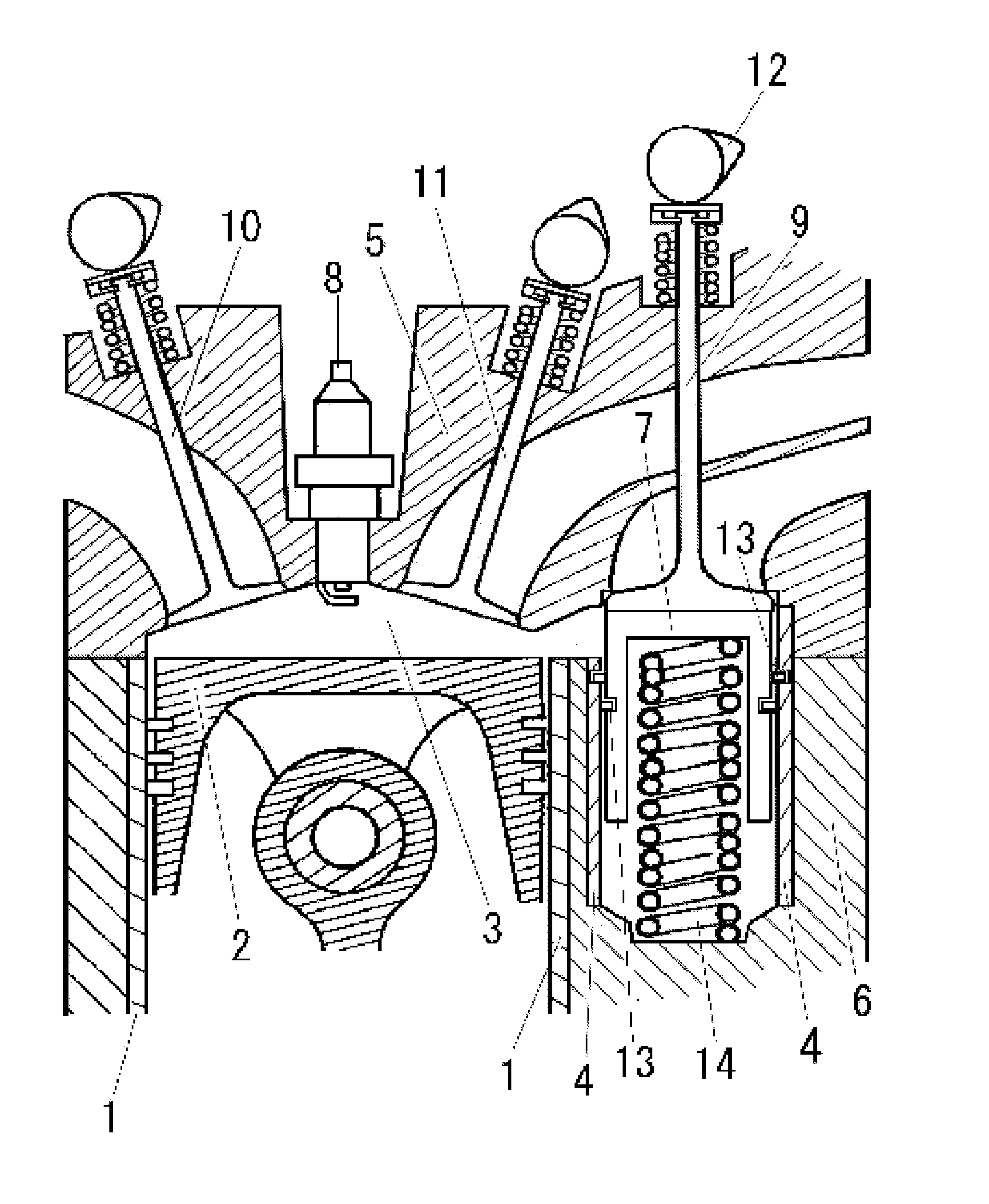
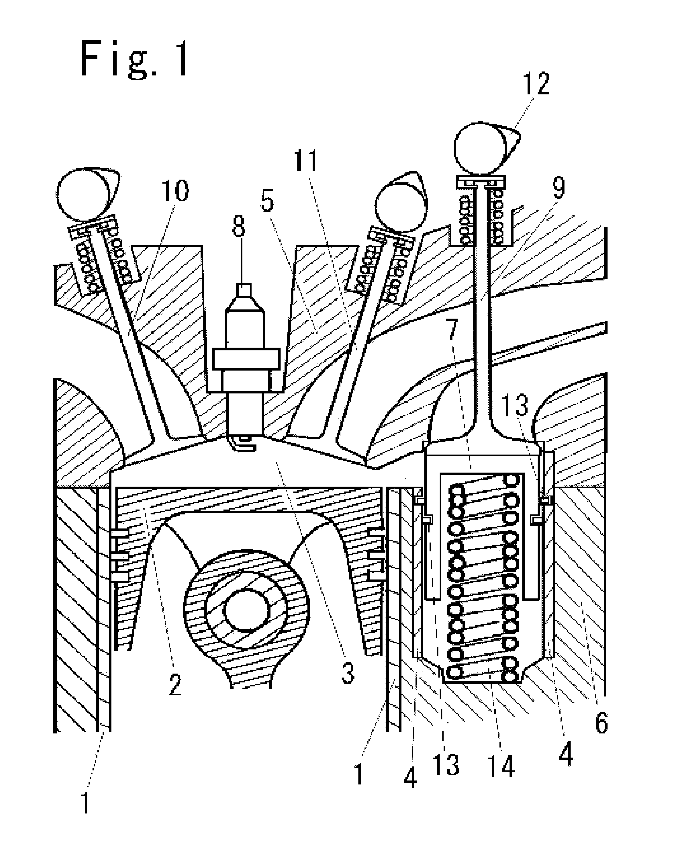
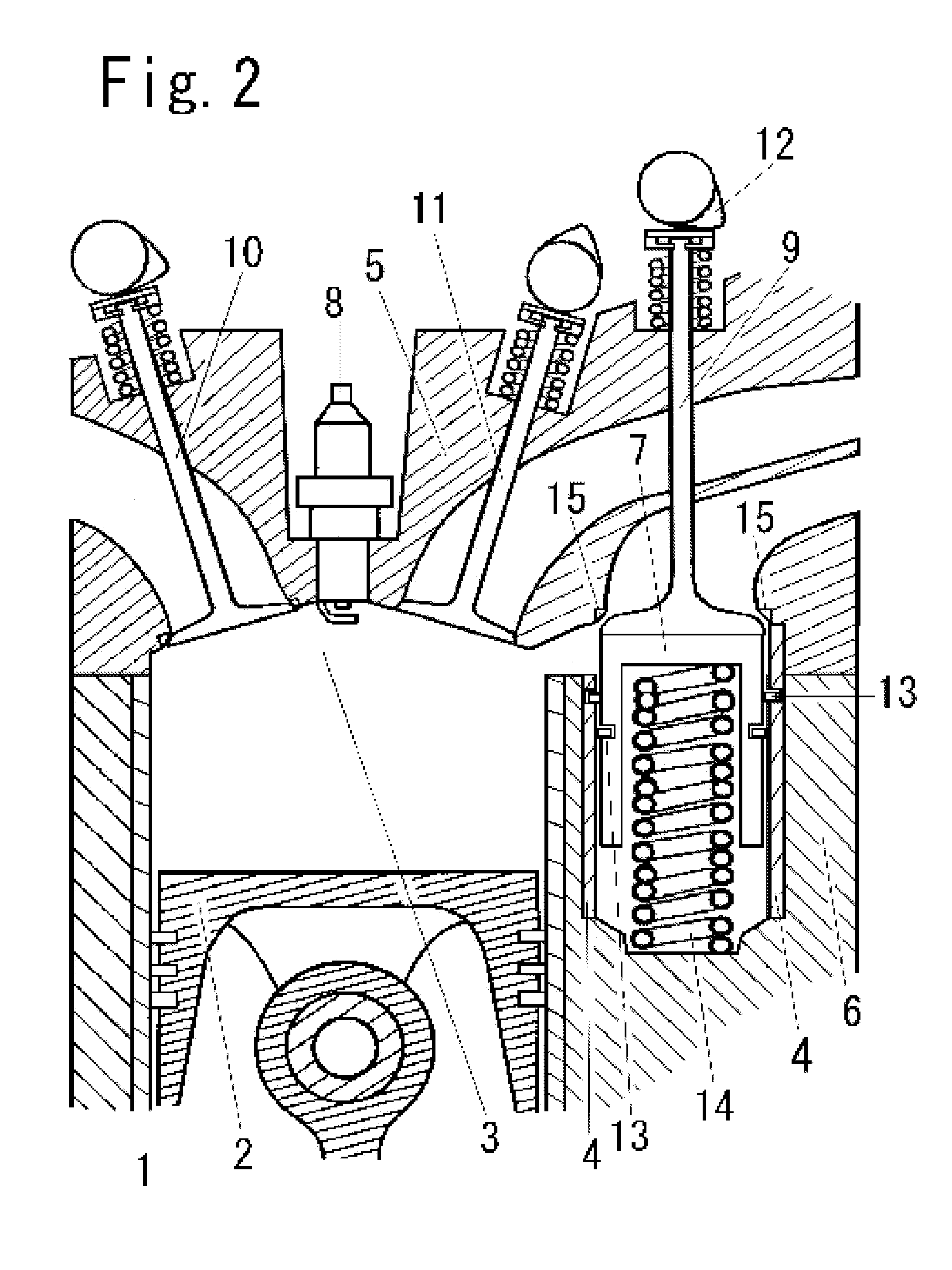
[0045]A spark ignition four-stroke cycle engine illustrated in FIGS. 1 to 4 comprises a cylinder head 5, a cylinder block 6, a main cylinder 1, a piston 2, a combustion chamber 3, an ignition plug 8, a sub-cylinder 4, a valve cover 7, an intake poppet valve 11, a first exhaust poppet valve 10 and a second exhaust poppet valve 9.

[0046]The piston 2 has a groove for a piston ring and reciprocates within the main cylinder 1. The combustion chamber 3 is formed between the cylinder head 5 and the piston 2. Further, the combustion chamber 3 is expanded out of the main cylinder 1.

[0047]The exhaust popper valve 9 is provided on a wall surface of the combustion chamber 3 expanded out of the main cylinder 1. One or more second exhaust poppet valves 9 may be provided.

[0048]The valve cover 7 has a cylindrical outer peripheral surface. The valve cover 7 reciprocates within the sub-cylinder 4. In order to bring an upper surface of the valve cover 7 i...

second embodiment

[0070]A second embodiment is now described below.

[0071]Hereinafter, only the difference between the first embodiment and the second embodiment is described.

[0072]Another example of the valve opening time for the second exhaust poppet valve 9 and the first exhaust poppet valve 10 is described.

[0073]In order to further reduce the temperature of the bottom surface of the first exhaust poppet valve 10, the first exhaust poppet valve 10 is preferably opened at a crank angle larger than that for the second exhaust poppet valve 9. If the valve opening time for the first exhaust poppet valve 10 is set in this manner, the gas pressure within the main cylinder may be too high after reaching the bottom dead center. In this manner, after reaching the bottom dead center of the exhaust stroke, an amount of exhaust loss work is increased.

[0074]In fact, it is required to seek the optimal valve opening time for the first exhaust poppet 10, which prevents the amount of exhaust loss work from increasi...

third embodiment

[0079]The above problem can be solved by a third embodiment described below referring to FIG. 4.

[0080]In the third embodiment, the following configurations are added to the first and second embodiments.

[0081]In the third embodiment, the positional relationship between the first exhaust poppet valve 10 and the intake poppet valve 11 is limited. In other words, the first exhaust poppet valve 10 is provided between the intake poppet valve 11 and the second exhaust poppet valve 9. The intake poppet valve 11 is not adjacent to the second exhaust poppet valve 9.

[0082]The end of the valve opening period for the second exhaust poppet valve 9 overlaps with the start of the valve opening period for the intake poppet valve 11. The period during which the second exhaust poppet valve 9 and the intake poppet valve 11 overlaps with each other is around the top dead center of the exhaust stroke. In FIG. 4, the top dead center of the exhaust stroke is illustrated.

[0083]The valve closing time for the...


PUM


Abstract

A second exhaust poppet valve 9 is provided in a portion of a combustion chamber expanded out of a main cylinder 1. A valve cover 7 reciprocates within a sub-cylinder 4 and covers a bottom surface of the second exhaust poppet valve 9. A first exhaust valve 10 and an intake poppet valve 11 are provided so as to face an upper surface of a piston 2. After the second exhaust poppet valve 9 is opened and hot high-pressure burned gas starts to flow away, the first exhaust poppet valve 10 is opened. As a result, the temperature of the first exhaust poppet valve 10 is reduced and the compression ratio can be increased. Then, a work amount of the piston is increased. The increased work amount compensates an amount of cooling loss due to increasing a surface area of the combustion chamber.

Description

BACKGROUND OF THE INVENTION[0001]1. Field of the Invention[0002]The present invention relates to compensating amount of cooling loss of a spark ignition four-stroke cycle engine whose combustion chamber is expanded out of a main cylinder.[0003]2. Description of the Related Art[0004]FIG. 5 shows an engine disclosed in FIG. 8 of Japanese Patent Application No. 2009-241923 (Japanese Patent No 4558090, hereinafter referred to as “Patent Document 1”). A combustion chamber of this engine is expanded out of its cylinder. A poppet valve and a sub-cylinder are provided in the expanded combustion chamber. A valve cover which covers a bottom surface of the poppet valve is inserted into the sub-cylinder. Therefore, in response to increasing a surface area of an inner wall of the combustion chamber expanded out of the cylinder, the heat dissipation area is increased and the cooling loss amount is increased.[0005]Increasing the cooling loss amount results in deteriorating the fuel consumption.[00...

Claims


Application Information

Patent Timeline
Patent Type & Authority Applications(United States)
IPC IPC(8): F02B75/02
CPCF02D13/0242F02D13/0257F02D13/0276F02D15/00Y02T10/12F01L2003/253F01L1/265F01L3/10F01L3/20F01L2003/25Y02T10/18
Inventor YAOITA, YASUHITO
Owner YAOITA YASUHITO
Why Eureka
Try Eureka