Lighting Device

a technology of light source and power supply, applied in the direction of electric variable regulation, process and machine control, instruments, etc., can solve the problems of low conversion efficiency, low power conversion efficiency, and inability to easily reduce internal power loss in principle, so as to improve power conversion efficiency and reduce power consumption. , the effect of stable driv

Inactive Publication Date: 2012-02-23
SEMICON ENERGY LAB CO LTD
View PDF6 Cites 5 Cited by
  • Summary
  • Abstract
  • Description
  • Claims
  • Application Information

AI Technical Summary

Benefits of technology

[0030]According to one embodiment of the present invention, a lighting device whose power conversion efficiency is improved and whose p

Problems solved by technology

Linear regulators have an advantage that noise is not easily generated; however, they have a disadvantage that internal power loss is not easily reduced in principle because desire output voltage is generated when input voltage is consumed using the on-resistance of elements.
Thus, conversion efficiency is low and the amount of heat generation associated with pow

Method used


Image

  • Lighting Device
  • Lighting Device
  • Lighting Device

Examples


embodiment 1

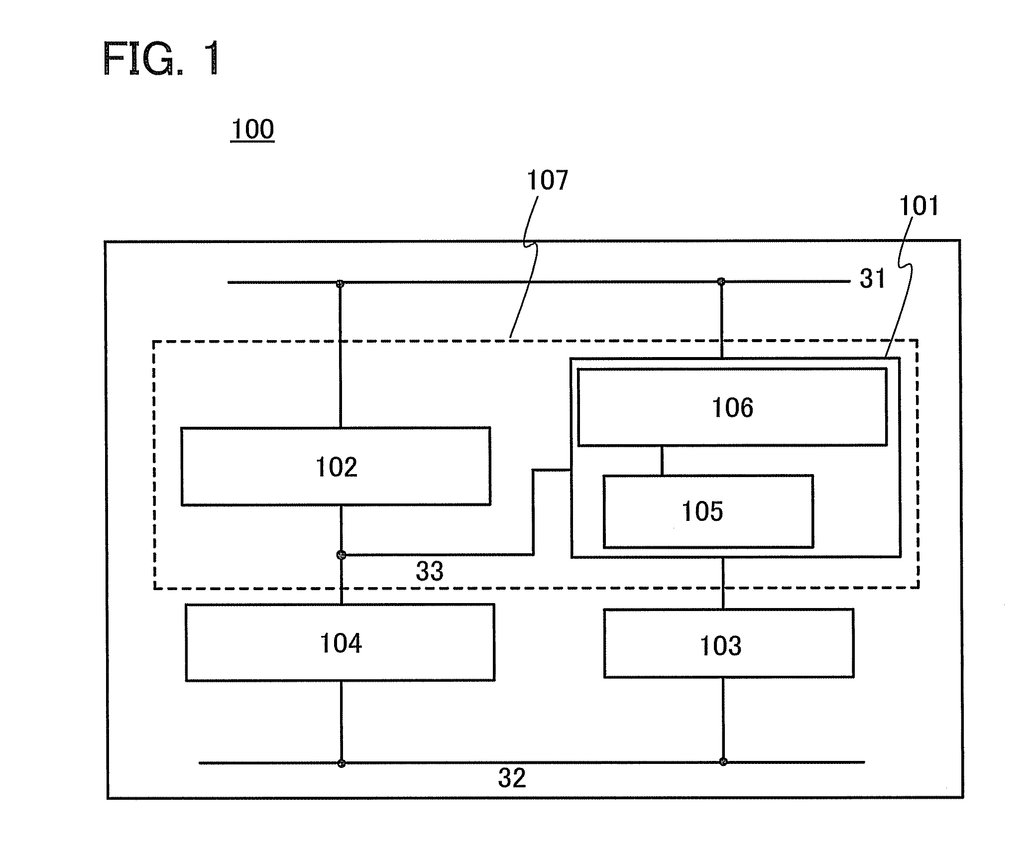
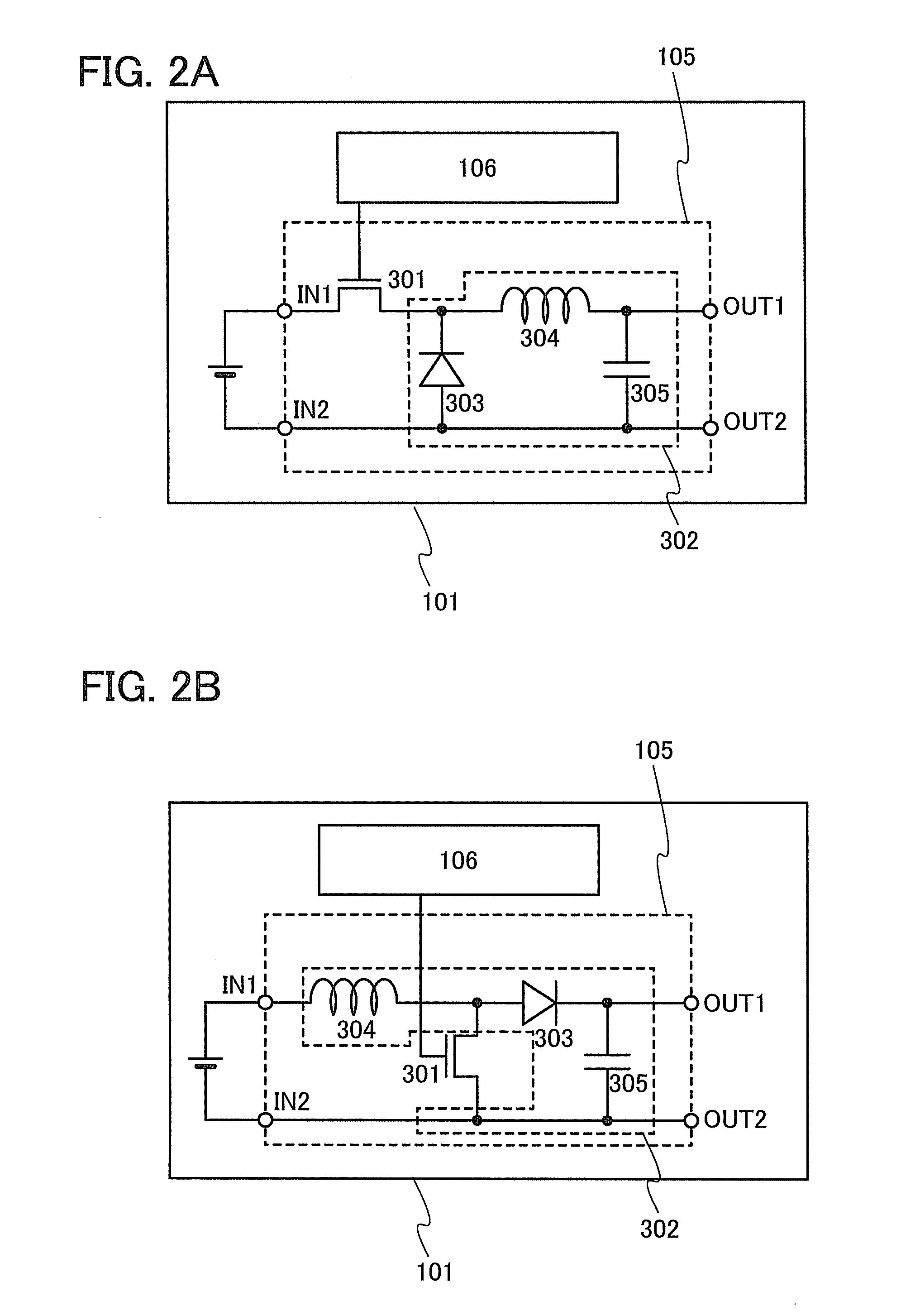
[0045]In this embodiment, circuit structures and operation of a lighting device according to one embodiment of the disclosed invention are described with reference to FIG. 1, FIGS. 2A and 2B, and FIG. 3.

[0046]A lighting device 100 illustrated in FIG. 1 includes a driver portion 107 that includes a voltage control switching regulator 101 and a constant current circuit 102, a light-emitting element 103, and a monitor light-emitting element 104.

[0047]A first power supply line 31 is electrically connected to an input terminal of the voltage control switching regulator 101 and the constant current circuit 102. One terminal of the light-emitting element 103 is electrically connected to an output terminal of the voltage control switching regulator 101. The other terminal of the light-emitting element 103 is electrically connected to a second power supply line 32. One terminal of the monitor light-emitting element 104 is electrically connected to the constant current circuit 102 and a third...

embodiment 2

[0090]In this embodiment, circuit structures and operation of a lighting device according to one embodiment of the disclosed invention are described with reference to FIG. 5 and FIG. 6.

[0091]A lighting device 400 illustrated in FIG. 5 includes a driver portion 408 that includes the voltage control switching regulator 101 and a current control switching regulator 401, the light-emitting element 103, and the monitor light-emitting element 104.

[0092]The first power supply line 31 is electrically connected to the input terminal of the voltage control switching regulator 101 and an input terminal of the current control switching regulator 401. The one terminal of the light-emitting element 103 is electrically connected to the output terminal of the voltage control switching regulator 101. The other terminal of the light-emitting element 103 is electrically connected to the second power supply line 32. The one terminal of the monitor light-emitting element 104 is electrically connected to...

embodiment 3

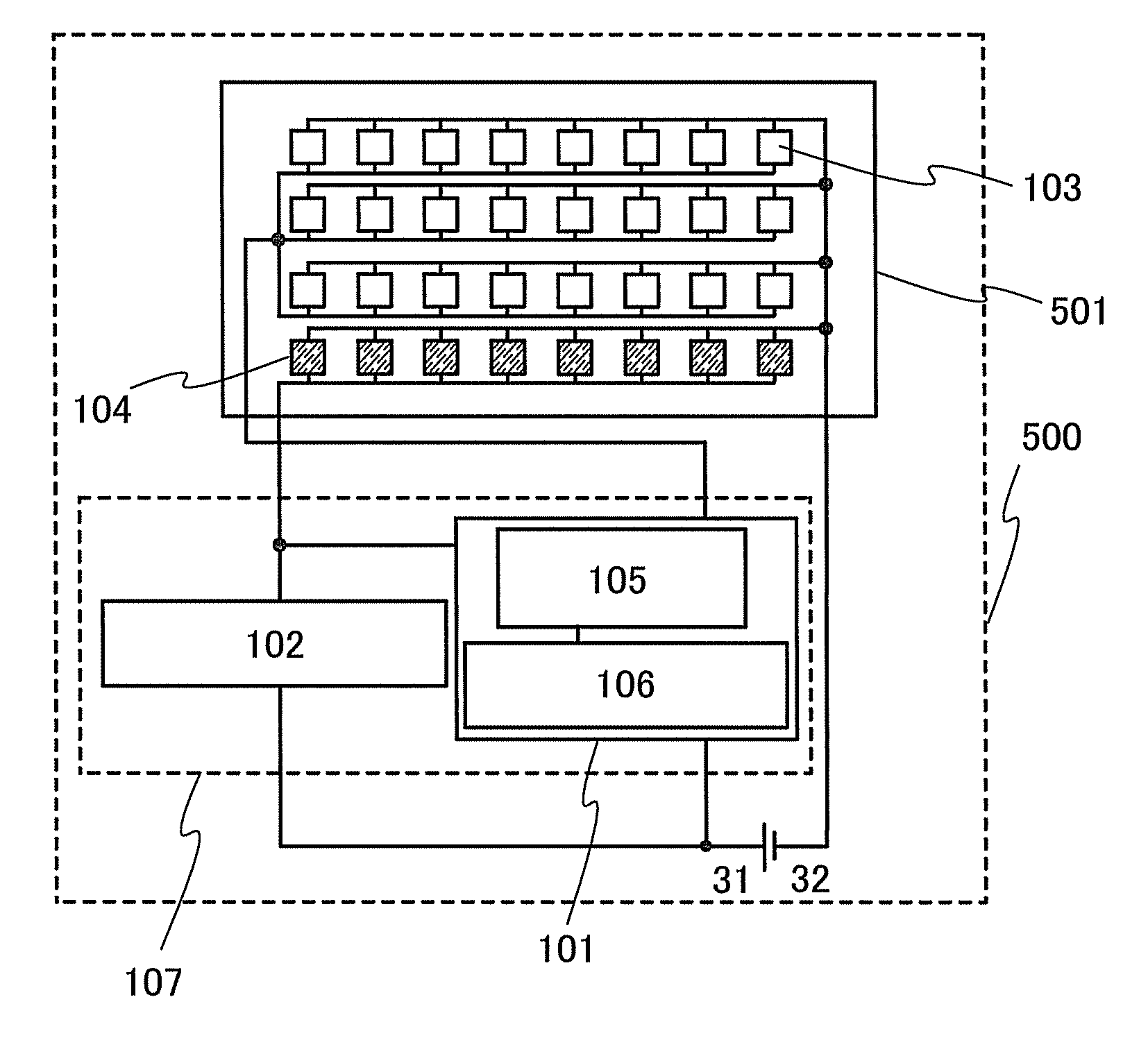
[0108]FIGS. 7A and 7B and FIGS. 8A and 8B are schematic plan views of the entire lighting device 500 according to the disclosed invention. FIGS. 7A and 7B are schematic plan views of the lighting device in which light-emitting elements are connected in parallel. FIGS. 8A and 8B are schematic plan views of the lighting device in which light-emitting elements are connected in series. Note that the light-emitting elements in the lighting device 500 are separately provided so that structures and connection relations of the light-emitting elements are easily understood. In each light-emitting element, an upper portion in the diagram corresponds to a cathode, and a lower portion in the diagram corresponds to an anode.

[0109]In FIGS. 7A and 7B, a substrate 501 includes the plurality of light-emitting elements 103 and the plurality of monitor light-emitting elements 104. Note that the number of the monitor light-emitting elements 104 is smaller than the number of the light-emitting elements ...


PUM


Abstract

A lighting device whose power conversion efficiency is improved by suppression of fluctuation in luminance of a light-emitting element and deterioration of the light-emitting element due to a change in temperature and a change over time and whose power consumption is reduced is provided. The disclosed invention is a lighting device that has a function of correcting a change in temperature and a change over time and includes at least one switching regulator in a driver portion. Constant current drive is performed on light-emitting elements and monitor light-emitting elements are used, so that highly-efficient output voltage which is corrected to have an optimal level is applied to the light-emitting elements and stable drive is performed for a long time. Power conversion efficiency is improved by a switching regulator, so that the total power consumption of the lighting device is reduced.

Description

BACKGROUND OF THE INVENTION[0001]1. Field of the Invention[0002]The disclosed invention relates to lighting devices including light-emitting elements, and display devices and electronic devices including lighting devices.[0003]2. Description of the Related Art[0004]In recent years, display devices and lighting devices that include light-emitting elements typified by organic EL (electroluminescence) elements emitting light at a luminance of 100 to 1000 cd / m2 have been developed. Broader applications have been expected by taking advantages of high image quality due to self emission, wide viewing angle, small thickness, lightweight, and the like. In particular, applications of organic EL elements to lighting equipment have been actively progressed. However, the life of organic EL elements and the emission efficiency of the organic EL elements decrease with a change over time. Thus, more improvement in luminance and more suppression of deterioration have been needed.[0005]The resistance...

Claims


Application Information

Patent Timeline
IPC IPC(8): H05B37/02
CPCY02B20/42G09G3/3225G09G2320/041G09G2320/043H05B37/02G09G2360/147G09G3/20G09G3/34H01L51/50G09G2330/00H05B47/10G09G3/30Y02B20/40H10K50/00
Inventor TAKAHASHI, KEI
Owner SEMICON ENERGY LAB CO LTD
Why Eureka
Try Eureka