Prostatic stent with localized tissue engaging anchoring means and methods for inhibiting obstruction of the prostatic urethra

a prostatic urethra and localized tissue technology, applied in the direction of prosthesis, contraceptive devices, catheters, etc., can solve the problems of increasing the risk of urinary tract infection, expanding or swelling of ablated tissue, and creating undesirable and unduly limited opening siz

Inactive Publication Date: 2004-04-06
JPMORGAN CHASE BANK AS ADMINISTATIVE AGENT
View PDF115 Cites 100 Cited by
  • Summary
  • Abstract
  • Description
  • Claims
  • Application Information

AI Technical Summary

Benefits of technology

It is therefore an object of the present invention to provide a stent which is suitable for inhibiting post thermal ablation obstruction in the prostate and which is configured in a minimally invasive manner to the wearer.
FIG. 11B is a side view of a pusher configured to be positioned inside of the stent to help position the stent in the body of the subject.

Problems solved by technology

Initially, the ablated tissue can expand or swell due to inflammation or edema which can undesirably block or obstruct the prostatic urethra.
Further, during the healing period, portions of the treated tissue can slough off and create an undesirable and unduly limited opening size.
While these type catheters allow the post-treatment catheter to be securely positioned relative to the bladder neck of the subject, natural operation of the sphincter is inhibited, and the configuration is relatively cumbersome (in position it extends through the penile urethra) and can be considered unduly invasive by the user and may increase the risk of urinary tract infection (UTI) when in position in the subject (particularly, when used for extended periods of time).
Other post-treatment catheter configurations (also known as "indwelling catheters" and "stents") have also been proposed; however, some of the catheter types can inhibit the ability to flush out blood clots which may exist from the therapy, and others are undesirably invasive to the user and / or prevent or inhibit the natural operation of the sphincter.
Still others are not able to be properly located within the prostatic cavity about the treatment region and / or are unable to retain their desired position in the prostate over time.

Method used


Image

  • Prostatic stent with localized tissue engaging anchoring means and methods for inhibiting obstruction of the prostatic urethra
  • Prostatic stent with localized tissue engaging anchoring means and methods for inhibiting obstruction of the prostatic urethra
  • Prostatic stent with localized tissue engaging anchoring means and methods for inhibiting obstruction of the prostatic urethra

Examples


Embodiment Construction

The present invention now will be described more fully hereinafter with reference to the accompanying drawings, in which embodiments of the invention are shown. This invention may, however, be embodied in many different forms and should not be construed as limited to the embodiments set forth herein; rather, these embodiments are provided so that this disclosure will be thorough and complete, and will fully convey the scope of the invention to those skilled in the art. In the figures, certain elements or features may be exaggerated for clarity. Like numbers refer to like elements throughout.

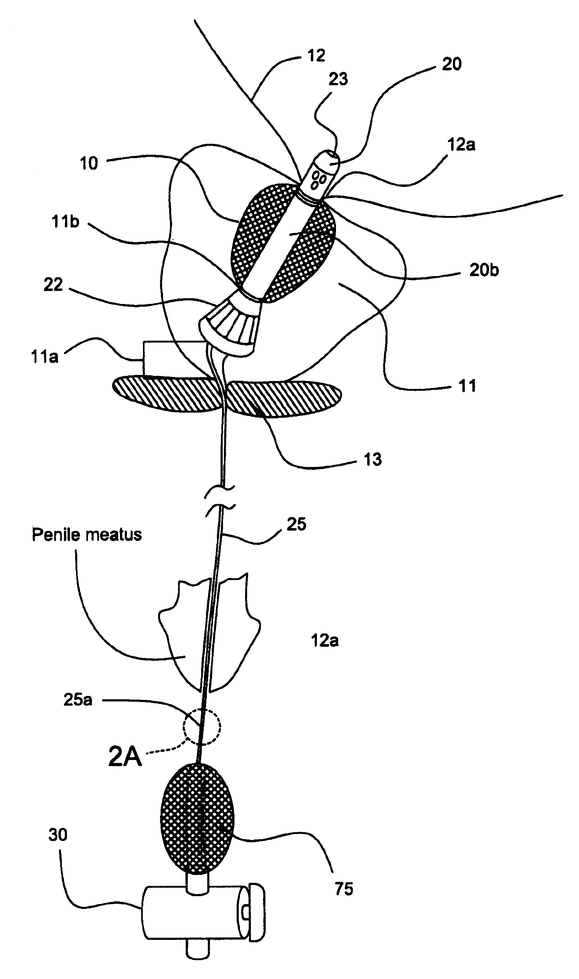
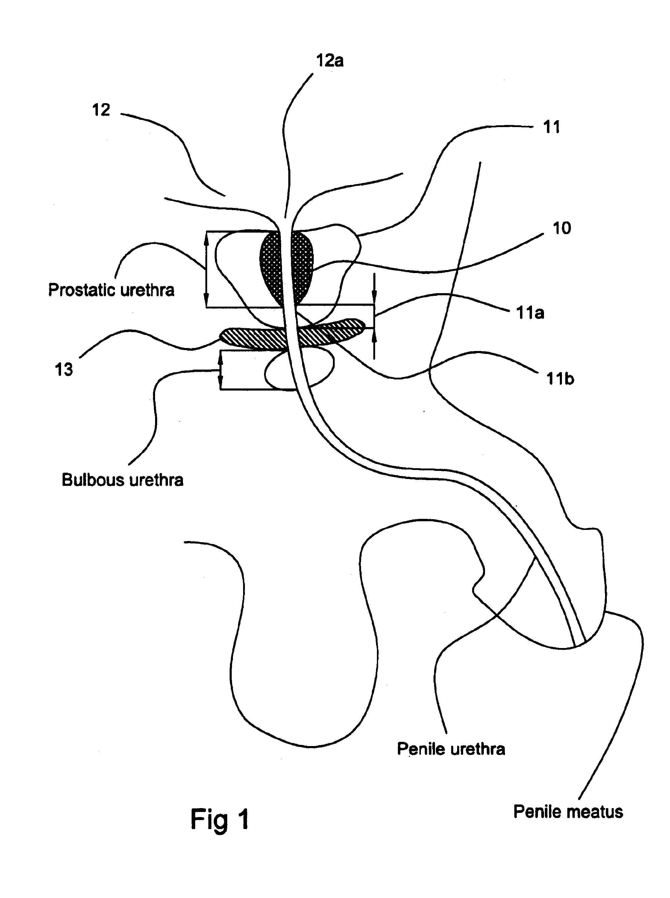
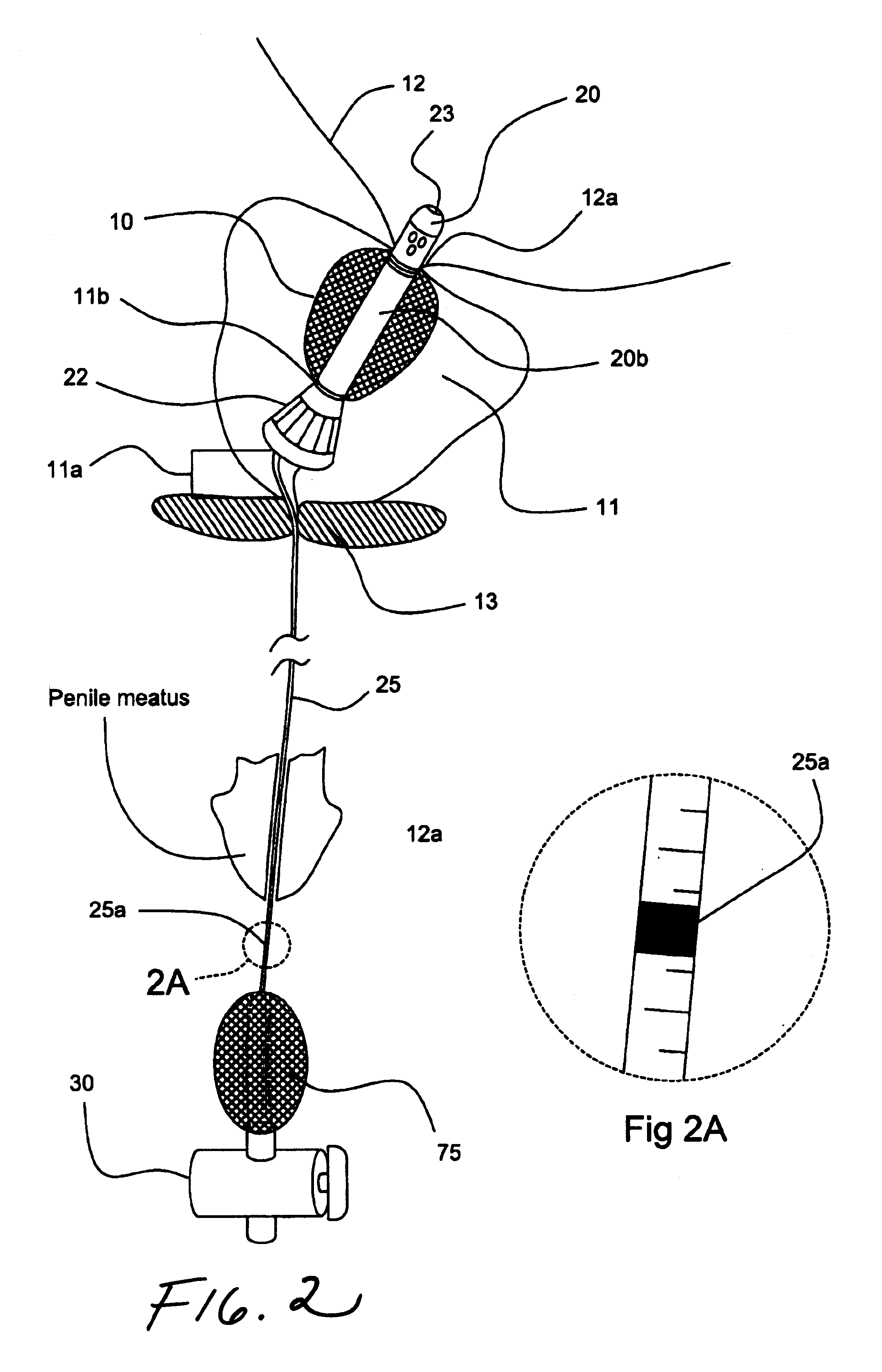
Referring now to FIG. 1, the thermal ablation treatment region 10 is indicated by the lined region in the prostate 11. The term "thermal ablation" refers to exposing the targeted tissue to a temperature which is sufficient to kill the tissue. In certain embodiments, the thermal ablation is carried out by exposing the targeted tissue to thermocoagulation via a catheter inserted into the subject wh...


PUM


Abstract

A prostatic stent is configured as a unitary body, which is adapted to reside above the sphincter when in position in a subject and allow normal functioning of the sphincter. The stent includes and elongated and substantially narrow conduit, which extends through the sphincter and outside the body of the subject. The conduit is sized and constructed to allow normal operation of the sphincter. The stent also includes and upper and / or an intermediate inflatable portions and may include a second conduit for the introduction of medication to the stent.

Description

The present invention relates to a stent configured for insertion into a lumen or body cavity of a subject.Conventionally, several types of thermal treatment systems have been proposed to treat certain pathologic conditions of the body by heating or thermally ablating targeted tissue. These thermal treatment systems have used various heating sources to generate the heat necessary to treat or ablate the targeted tissue. For example, laser, microwave, and radio-frequency (RF) energy sources have been proposed to produce the heat which is then directed to the targeted tissue in or around the selected body cavity. Thermal treatment systems have been used to thermally ablate the prostate (as well as other organs, body cavities, and / or natural lumens).One particularly successful thermal ablation system is directed to thermally ablating the prostate by a thermocoagulation process. This thermal ablation system employs a closed loop liquid or water-induced thermotherapy (WIT) system which he...

Claims


Application Information

Patent Timeline
Patent Type & Authority Patents(United States)
IPC IPC(8): A61M25/10A61B17/22A61B18/14A61F2/00A61B17/00A61M1/00A61F2/848A61F7/12A61M25/00
CPCA61M25/1011A61B18/1492A61B2017/00274A61B2017/22069A61B2018/00547A61F2/0027
Inventor LAZAROVITZ, JACOBCIOANTA, IULIANKLEIN, RICHARD BARRY
Owner JPMORGAN CHASE BANK AS ADMINISTATIVE AGENT
Why Eureka
Try Eureka