Arterial spin labeling using time varying gradients

Inactive Publication Date: 2004-04-06
BETH ISRAEL DEACONESS MEDICAL CENT INC
View PDF11 Cites 30 Cited by
  • Summary
  • Abstract
  • Description
  • Claims
  • Application Information

AI Technical Summary

Benefits of technology

The control RF irradiation may further be frequency modulated. An envelope for frequency modulation of the control RF irradiation may be similar to the envelope for amplitude modulation of the control RF irradiation. In one embodiment of the invention, the envelope for amplitude modulation of the control RF irradiation may be a modified square wave. The envelope for the label RF irradiation may be the absolute value of the modified square wave.
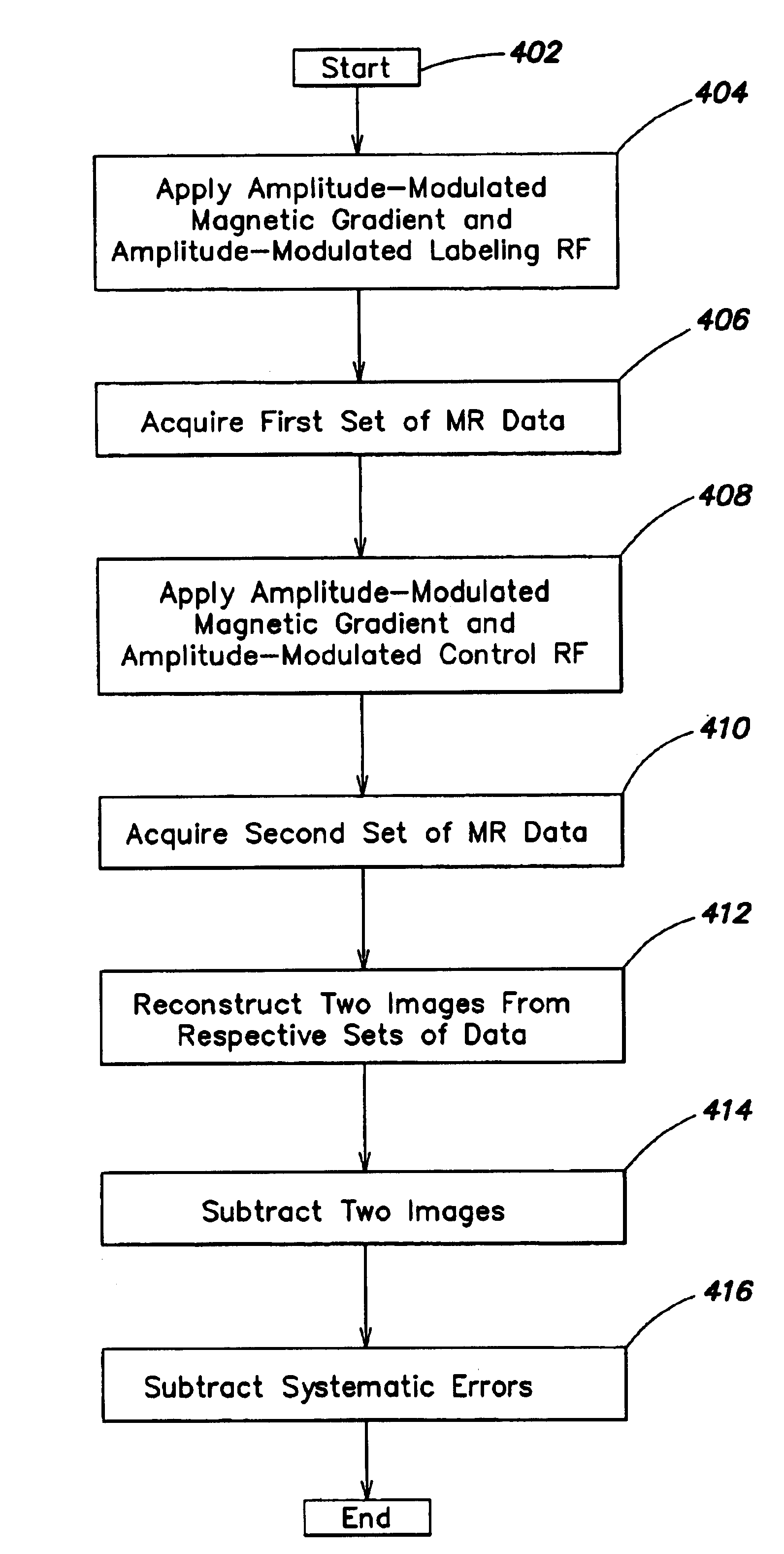
An image of fluid flow may be generated by subtracting the label dataset from the control dataset. In an alternative embodiment of the invention, the image of the fluid flow may further be modified by subtracting artifacts of systematic errors from the image.
Another aspect of the invention is a method for compensating for magnetization transfer effects by applying an amplitude modulated magnetic field gradient and amplitude modulated RF irradiation during a label procedure and applying an amplitude modulated control magnetic field gradient and amplitude modulated control RF irradiation during a control procedure. Such compensation for the magnetization transfer effects may be performed in a context of an MR study, such as, for example, an MR imaging study. Furthermore, RF irradiation may be frequency modulated during the label and / or control experiments. An envelope for label RF irradiation for frequency and amplitude modulation may be similar and may be similar to an envelope for amplitude modulation for label magnetic field gradient. An envelope for control RF irradiation for frequency and amplitude modulation may be similar and may be similar to an envelope for amplitude modulation of the control magnetic field gradient. The envelope for label RF irradiation modulation may be an absolute value of the envelope for the control RF irradiation. The envelope for the control RF irradiation may be a modified square wave. In an alternative embodiment, the envelope for the control RF irradiation may be a function other than the square wave, as long as an average control RF irradiation amplitude is at or near zero.
In yet another aspect of the invention, a magnetic resonance apparatus may be constructed and arranged to perform fluid flow imaging. Such apparatus may apply amplitude modulated label RF irradiation and a magnetic field gradient during the labeling procedure. Furthermore, such apparatus may apply amplitude modulated label RF irradiation and a magnetic field gradient during the control procedure. The envelope for applied control magnetic field gradient may be similar or identical to the envelope for applied control RF irradiation. The envelope for applied label RF irradiation and the magnetic field gradient may be the absolute value of the envelope for the control RF irradiation.
In yet another embodiment of the invention, a computer readable medium may be provided. Encoded on the computer readable medium may be instructions that, when executed, direct a method for generating an image of fluid flow obtained from a magnetic resonance system. Such a method may comprise combining a control image received from the control procedure where the amplitude modulated RF irradiation and the magnetic field gradient were applied with a label image received from the labeling procedure where the amplitude modulated RF irradiation and the magnetic field gradient were applied. The control and label images may be combined to create the image of fluid flow by subtracting the label image from the control image.
In another embodiment of the invention, the image of the fluid flow may be further modified by subtracting artifacts of residual or system errors. A dataset for the residual or system errors may be obtained by performing labeling and control procedures in a region different from the region being imaged such as upstream or downstream from the region being imaged. The fluid flow image may be further modified as appropriate for a particular application.

Problems solved by technology

However, magnetization transfer effects and other unrelated errors may interfere with the procedure by causing more than just the "upstream" fluid to be labeled.

Method used


Image

  • Arterial spin labeling using time varying gradients
  • Arterial spin labeling using time varying gradients
  • Arterial spin labeling using time varying gradients

Examples


first embodiment

FIG. 6 is a diagram of a frequency modulation envelope for labeling and control RF irradiation. In one first embodiment of the invention previously described, frequency modulation envelopes 602 and 604 are similar to amplitude modulation envelops 502 and 504, respectively. However, the invention is not limited to such envelopes. In an alternative embodiment of the invention, frequency modulation envelopes may be different from amplitude modulation envelopes. Furthermore, frequency modulation envelope 602 for labeling RF irradiation need not be an absolute value of the control RF irradiation envelope 604. In general, frequency and amplitude modulation envelopes 502, 504, 602, and 504 may be varied depending on requirements of the particular application, as deemed appropriate by one skilled in the art.

In one embodiment of the invention illustrated in FIGS. 5 and 6, both amplitude and frequency modulation is fast compared to T2, in order to avoid decreases in efficiency due to transver...


PUM


Abstract

The present invention relates to a method and system for conducting a magnetic resonance fluid flow study by conducting a labeling procedure and a control procedure and combining datasets from those procedures to create a dataset for the fluid flow study. An amplitude modulated magnetic field gradient and amplitude modulated RF irradiation may be applied during a labeling procedure. Likewise, amplitude modulated RF irradiation may be applied during a control procedure. An amplitude modulated magnetic field gradient may also be applied during the control procedure.

Description

FIELD OF THE INVENTIONThe present application relates to a technique for imaging fluid flow noninvasively using MRI with radio frequency arterial spin labeling and, more particularly, to a labeling technique that permits extension of this technique to a multislice or volume examination.BACKGROUND OF THE INVENTIONMagnetic Resonance Imaging (MRI) is an imaging technique used primarily in medical settings to produce high quality images of the inside of the human body. MRI is based on principles of nuclear magnetic resonance (NMR), a spectroscopic technique used to obtain microscopic chemical and physical information about molecules.MR (magnetic resonance) techniques may be used to study fluid flow, such as, for example, blood flow and blood perfusion in tissue. One of many possible applications is to study blood perfusion in the human brain.Typically, during MR studies, images are taken of a volume of interest or of "slices" in a region of interest. A slice may be defined as a relative...

Claims


Application Information

Patent Timeline
Patent Type & Authority Patents(United States)
IPC IPC(8): G01R33/54G01R33/563
CPCG01R33/56308G01R33/56366
Inventor ALSOP, DAVID
Owner BETH ISRAEL DEACONESS MEDICAL CENT INC
Why Eureka
Try Eureka