

Polarized light irradiation apparatus
a technology of polarized light and irradiation apparatus, which is applied in the direction of polarising elements, instruments, printing, etc., can solve the problems of reducing the ratio and unable to achieve the desired extinction ratio
- Summary
- Abstract
- Description
- Claims
- Application Information
AI Technical Summary
Benefits of technology
Problems solved by technology
Method used
Image

Examples
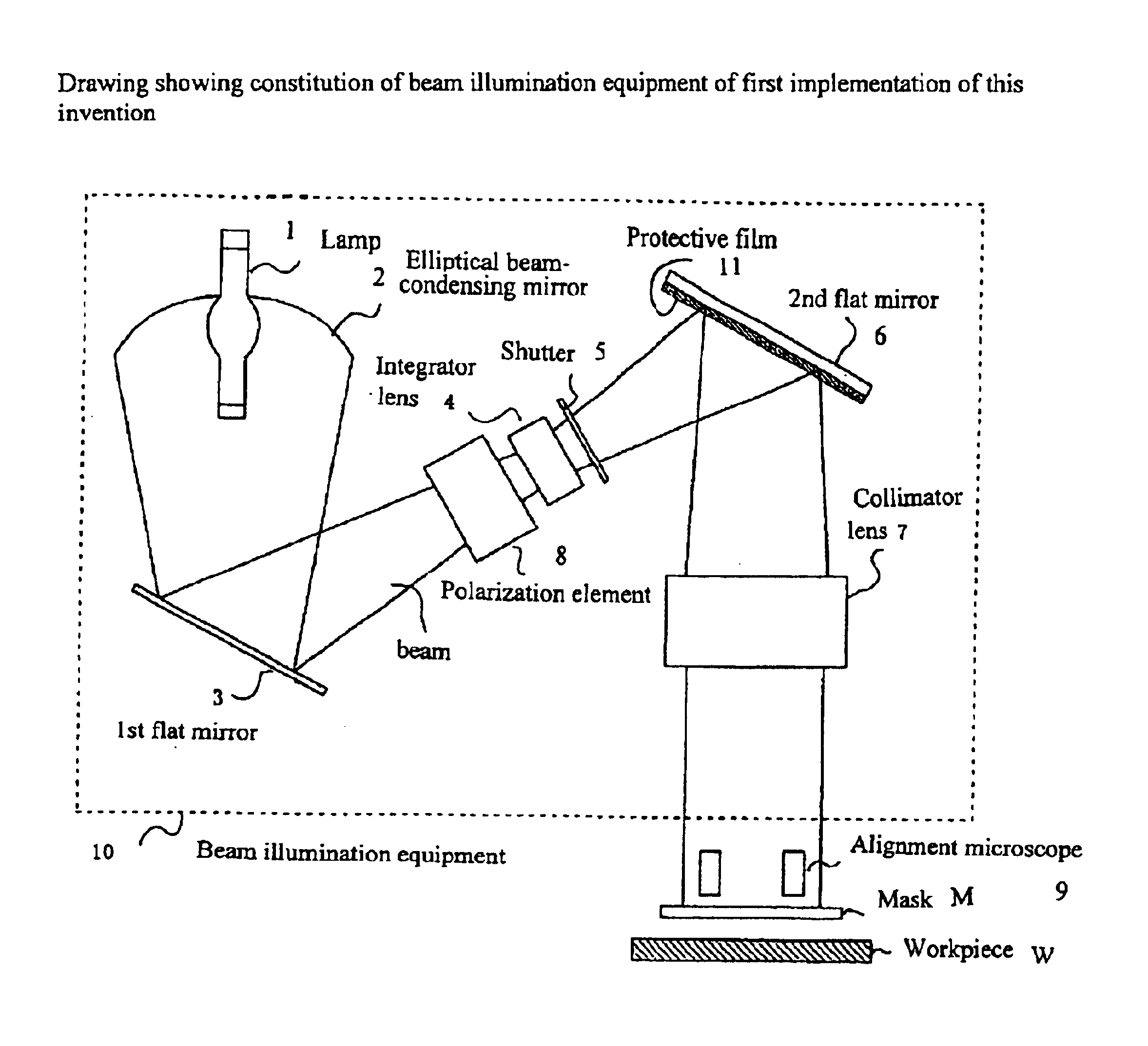
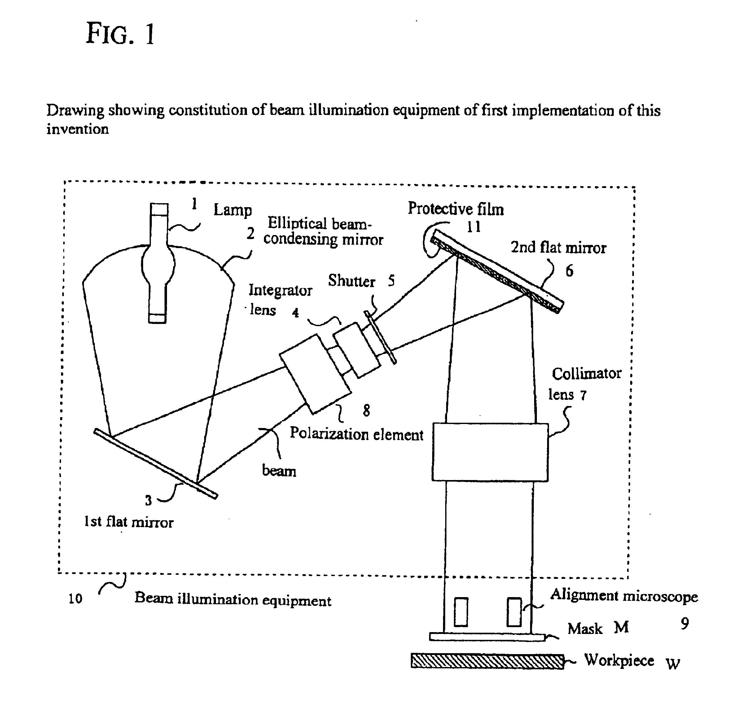
first embodiment
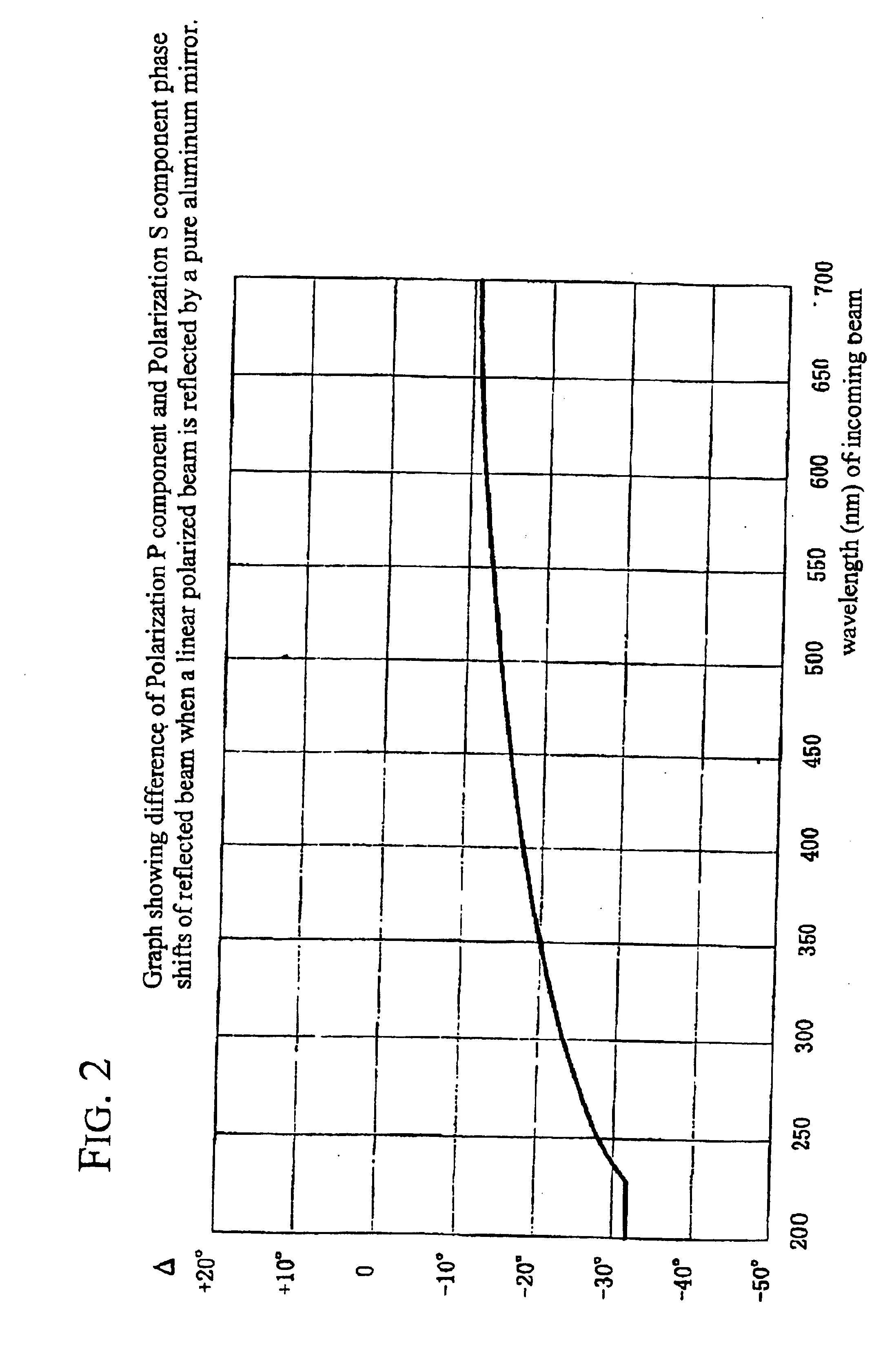
the polarized light irradiation apparatus of the invention is shown in FIG. 1. In FIG. 1, the element identified are the same as those in FIG. 11, but in this embodiment, the surface of the second plane mirror 6 has been treated with a dielectric layer (protection layer) 11. The material of the dielectric layer and its thickness are selected, in connection with the angle of incidence of the polarized light on the second plane mirror 6 and the wavelength needed to align the optical alignment layer formed on the workpiece W, so that the difference in phase shifts .DELTA. of the polarization P component and polarization S component of the polarized light that reflects is no greater than 20.degree.. The second plane mirror 6 is, for example, an aluminum mirror, and the dielectric layer 11 formed on its surface (hereafter protection layer 11) can be, for example, a magnesium fluoride (MgF.sub.2) layer or a silicon dioxide (SiO.sub.2) layer.
In FIG. 1, the light from the lamp 1 is condense...
PUM
| Property | Measurement | Unit |
|---|---|---|
| thickness | aaaaa | aaaaa |
| thickness | aaaaa | aaaaa |
| wavelength | aaaaa | aaaaa |
Abstract
Description
Claims
Application Information