Apparatus for cooling fuel and fuel delivery components

a technology for cooling fuel and components, applied in the direction of combustion engines, combustion-air/fuel-air treatment, charge feed systems, etc., can solve the problems of largely ineffective efforts, lack of several elements in prior art, and elimination of advantages

Inactive Publication Date: 2004-04-13
RYON LEE S
View PDF10 Cites 21 Cited by
  • Summary
  • Abstract
  • Description
  • Claims
  • Application Information

AI Technical Summary

Problems solved by technology

Failure to supply enough cooling for the fuel close to the intake manifold means that the injectors, carburetor(s) or throttle bodies which introduce fuel into the intake manifold (collectively referred to herein as "fuel delivery components") results in the fuel delivery components acting as a heat exchange for the fuel.
Thus, hot fuel delivery components increase the fuel temperature and eliminate the advantage of any efforts to cool the fuel upstream in the fuel system.
These efforts have largely been ineffective because the devices or practices have not delivered enough cooling at the right location, i.e., just prior to entry of the fuel into the fuel delivery components.
The prior art, however, suffers the disadvantage of lacking several elements of the present invention including, without limitation, a second cooling fluid system comprised of a cooling fluid radiator and cooling fluid pump.
Additionally, none of the prior art cools the fuel delivery components to provide an additional buffer of cooling so as to minimize heat re-absorption after initial cooling of the fuel.
The lack of an effective fuel cooling apparatus in the prior art is manifested in part by the existence of various stop-gap methods of fuel cooling among racing enthusiasts such as refrigerating fuel cans with ice.
Nitrous oxide, however, is a drastic form of cooling, and can only be used briefly and in high gears because it produces extreme cooling and a tremendous spike in engine performance.

Method used


Image

  • Apparatus for cooling fuel and fuel delivery components
  • Apparatus for cooling fuel and fuel delivery components
  • Apparatus for cooling fuel and fuel delivery components

Examples


Embodiment Construction

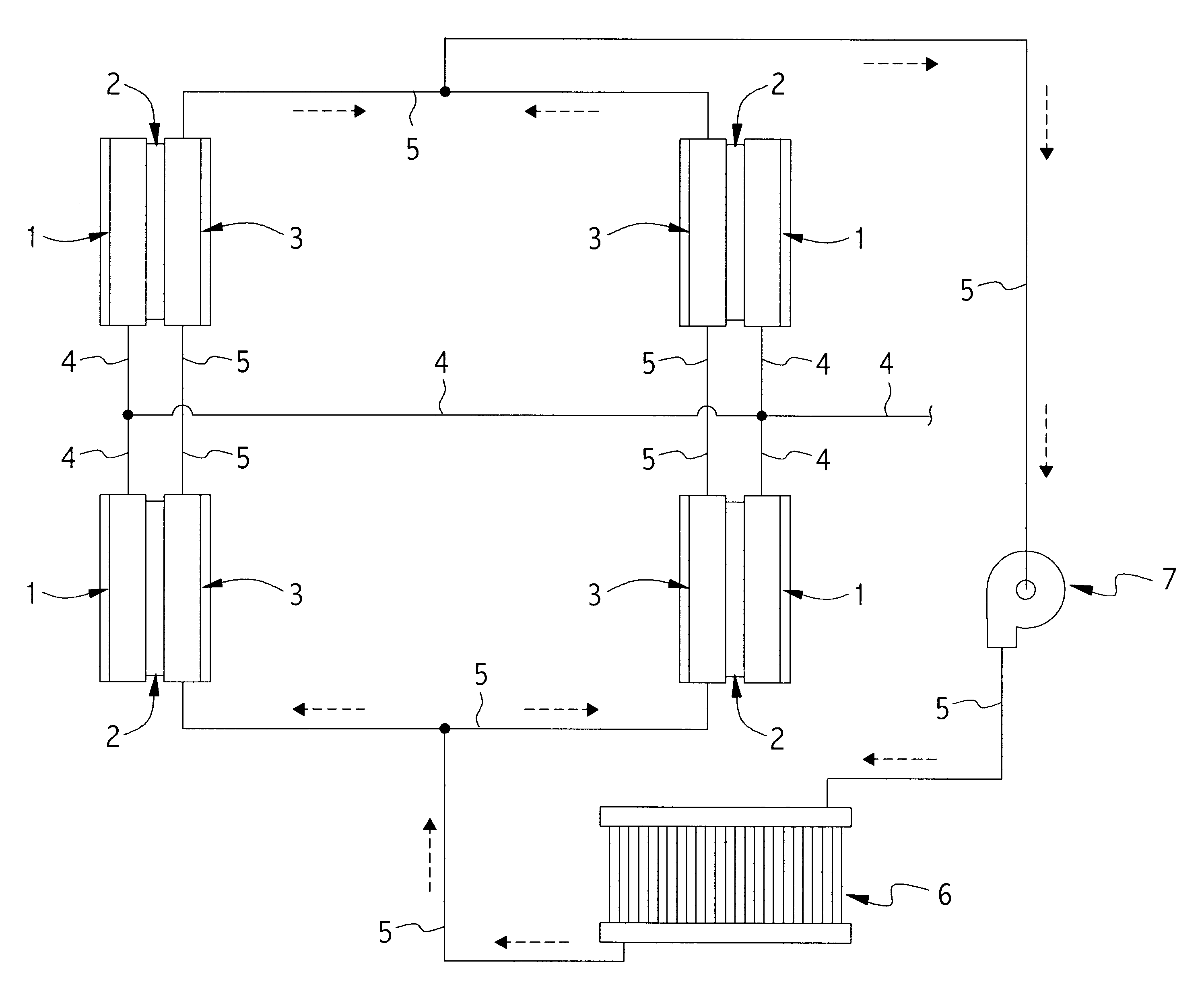
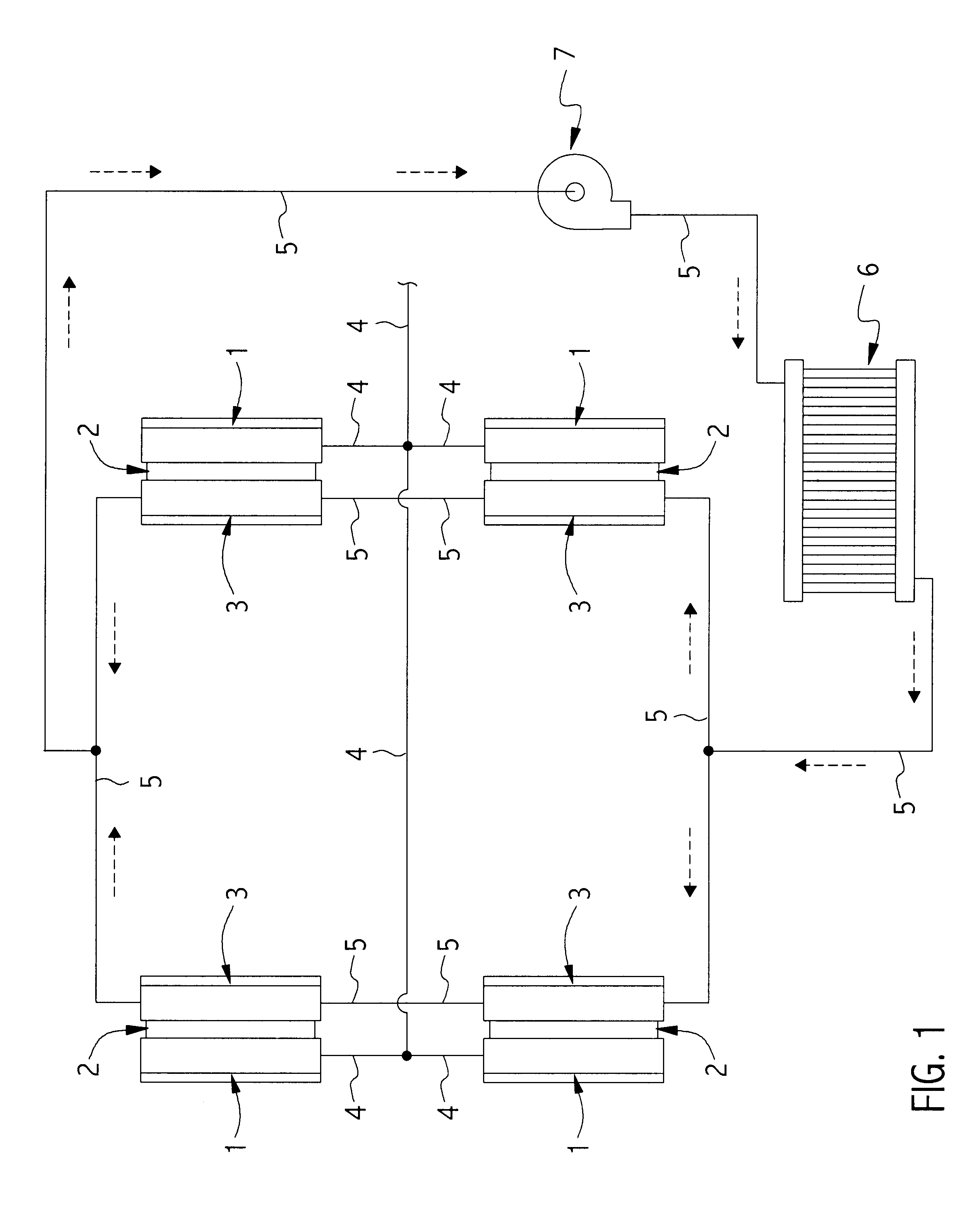
The cooling apparatus is shown in schematic layout surrounding the intake manifold in an eight cylinder engine block in FIG. 1, in which four of the fuel cooling blocks 1 are shown as mounted adjacent to the cold side of thermoelectric units 2 and the cooling fluid blocks 3 are mounted adjacent to the hot side of the thermoelectric units. The fuel line 4 connects the fuel cooling blocks 1 to the fuel pump and fuel tank which are not pictured. The cooling fluid line 5 connects the cooling fluid blocks 3 to the cooling fluid radiator 6, which is an additional radiator distinct from that used in the engine cooling system, which is not pictured. A cooling fluid pump 7 assures controlled flow of the cooling fluid.

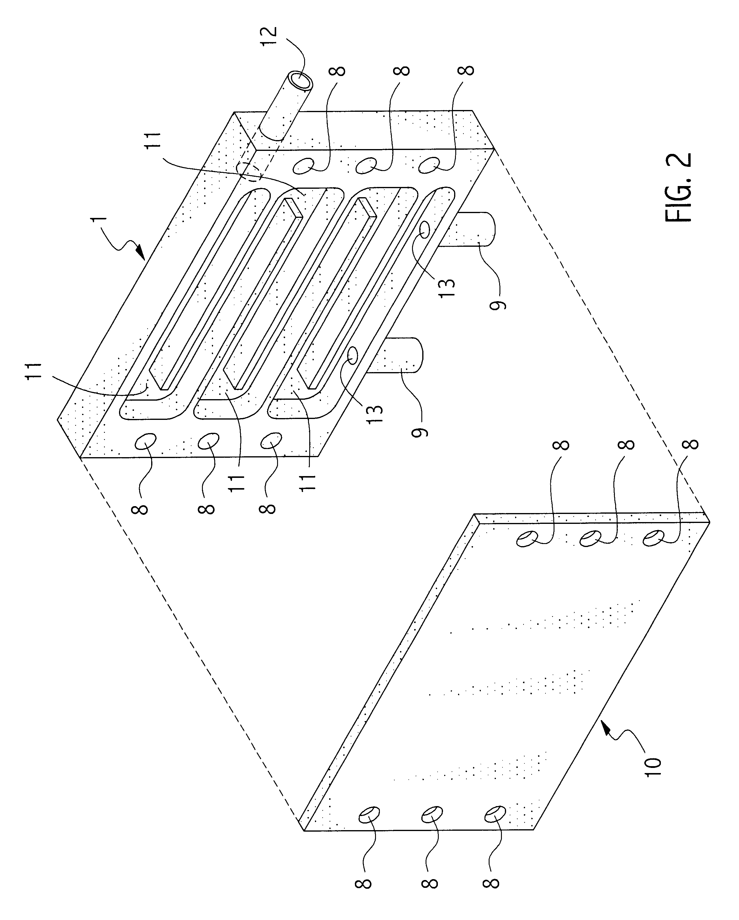
FIG. 2 is an exploded view of the fuel-cooling block 1 in a multi-piece configuration and the fuel-cooling block sealing plate 10 showing holes 8 for mounting of screws 19 (see FIG. 4) to secure the fuel-cooling block 1 to the thermoelectric unit 2. Fuel enters the fuel cooling ...


PUM


Abstract

An apparatus is disclosed for cooling fuel by means of the cold side of a thermoelectric unit just prior to entry of the fuel into the fuel delivery components (injectors, carburetors and throttle bodies). An excess of cooling is supplied sufficient to cool the fuel delivery components so as to provide an additional buffer of cooling for the fuel and to prevent substantial re-absorption of heat after the fuel is cooled. The hot side of the thermoelectric unit is cooled by a secondary cooling fluid system separate and distinct from the principal cooling fluid system for the engine block. In one embodiment, excess fuel is shunted by a fuel bypass pressure regulator to a fuel bypass line, and the excess fuel is the cooling fluid which is returned to the fuel tank.

Description

1. FIELD OF THE INVENTIONThe present invention is a novel apparatus for cooling fuel for internal combustion engines, as well as cooling the fuel delivery components which are the fuel injectors, carburetors and throttle bodies.2. BACKGROUND OF THE INVENTIONAuto-ignition or pre-ignition diminishes engine performance because excessive pressure or heat inside the cylinder causes the fuel / air mix to fire at inopportune times. See Taylor, Internal Combustion Engine in Theory and Practice, 40-41, 84 (MIT Press Rev. Ed. 1985). One effort to reduce cylinder temperature addressed the concern of auto-ignition by reversing the flow of fluid from the radiator so that the coolest fluid entered the hottest part of the engine block, so as to cool the cylinder walls. See Lumley, Engines: An Introduction, 95-96 (Cambridge Univ. Press: 1999). Cooler fuel / air mix inside the cylinders helps to insure ignition will occur when the spark is delivered by the timing mechanism, thus producing optimal perfor...

Claims


Application Information

Patent Timeline
Patent Type & Authority Patents(United States)
IPC IPC(8): F02M31/00F02M31/20
CPCF02M31/20Y02T10/126Y02T10/166Y02T10/12
Inventor RYON, LEE S.
Owner RYON LEE S
Why Eureka
Try Eureka