Valve and vacuum processing device with the valve

a processing device and valve technology, applied in the direction of spindle sealing, valve operating means/releasing devices, spindle types, etc., can solve the problems of vacuum breakage, corroded section of sealing mechanism, corroded sealing mechanism, etc., to prevent corrosion of sealing mechanism

Inactive Publication Date: 2004-04-13
TOKYO ELECTRON LTD
View PDF12 Cites 10 Cited by
  • Summary
  • Abstract
  • Description
  • Claims
  • Application Information

AI Technical Summary

Benefits of technology

An object of the present invention is to provide valve which can certainly prevent corrosion of a sealing mechanism for sealing a valve main body air-tightly with respect to a drive mechanism side, as well as the drive mechanism, and further can certainly prevent an operational error caused by particles contained in gas, thereby achieving a gas leakage proof and vacuum break proof, and a vacuum processing apparatus comprising such a valve.

Problems solved by technology

As described above, in the conventional valve, the anti-corrosive measures are not taken for the sealing mechanism, and therefore the seal mechanism is corroded with corrosive gases such as process gas and reaction byproducts.
As a result, there is a danger of vacuum break caused from a corroded section of the sealing mechanism.
Further, the reaction byproducts flowing through the gas exhaustion pipe 3 contains particles, and the seal mechanism may clog with some of the particles, thereby causing an operational error of the valve member or vacuum break.

Method used


Image

  • Valve and vacuum processing device with the valve
  • Valve and vacuum processing device with the valve
  • Valve and vacuum processing device with the valve

Examples


Embodiment Construction

Embodiments of the present invention will now be described with reference to the drawings.

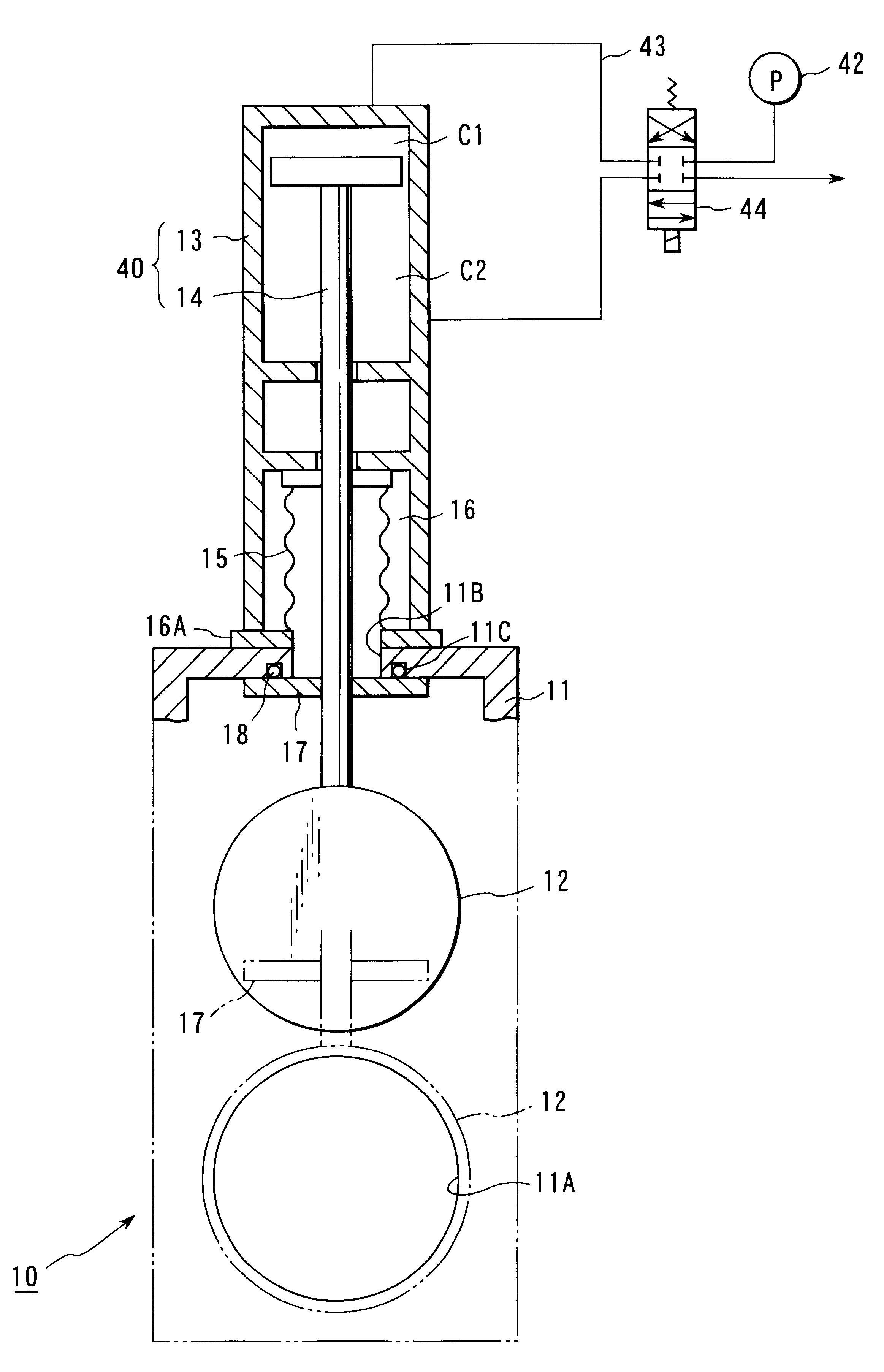
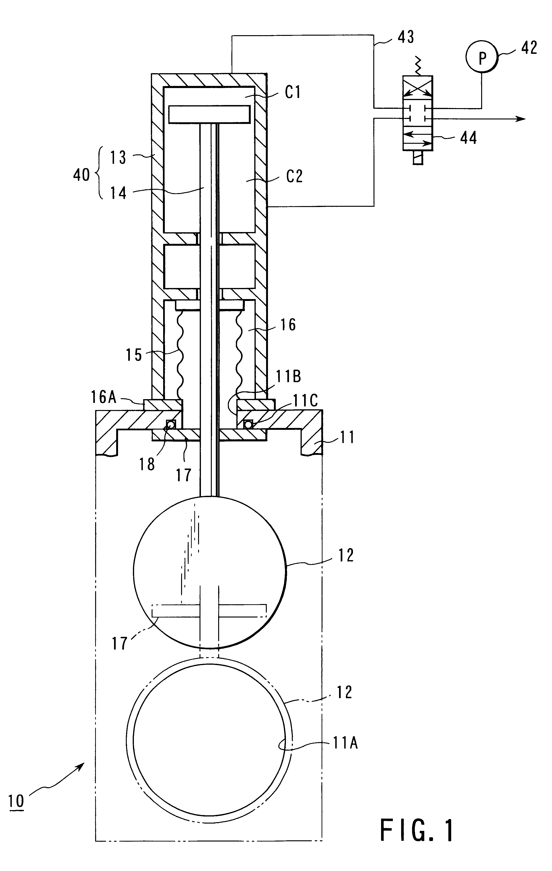
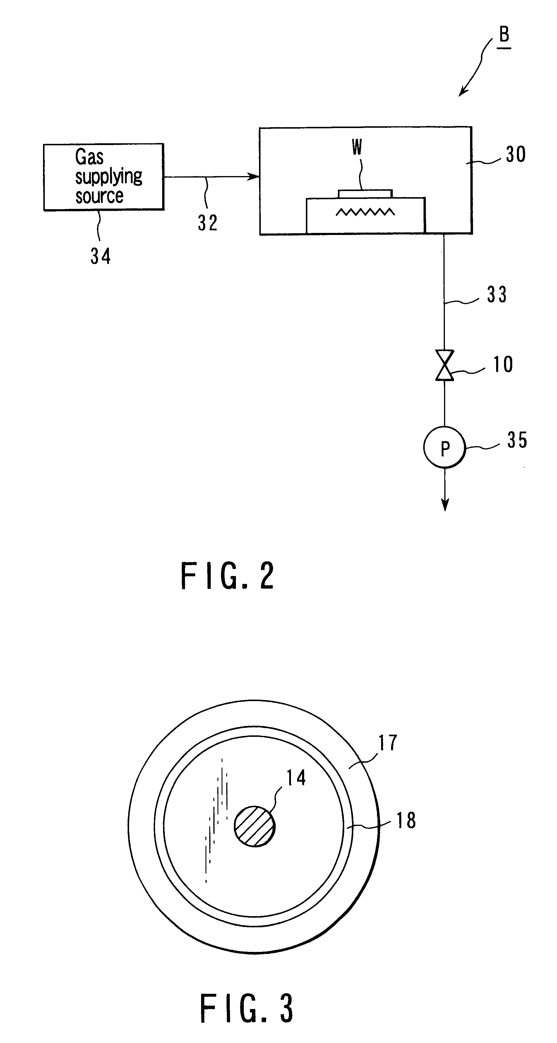
FIGS. 1 and 2 show the first embodiment of the present invention. As shown in FIG. 2, a vacuum processing apparatus B of this embodiment includes a processing chamber 30 for carrying out a predetermined processing on an object W to be processed with use of a process gas under a predetermined vacuum atmosphere, a plurality of gas supplying pipes 32 and a gas exhaustion pipe 33, both connected to the processing chamber 30, and a valve 10 mounted on the gas exhaustion pipe 33. The processing chamber 30 is connected to another chamber, which is not shown, such as a transfer chamber. The gas supplying pipe 32 is connected to a gas supplying source 34 for supplying the process gas. Further, the gas exhaustion pipe 33 is connected to the vacuum pump 35.

In the processing apparatus B described above, a process gas is supplied into the processing chamber 30 from the gas supplying source 34 via the gas su...


PUM


Abstract

The valve 10 includes a valve main body 11 having an opening 11A and forming a space which creates a part of a gas flow path, a first valve member 12, provided in the valve main body, for opening/closing the opening 11A, and a drive mechanism 40 for moving the first valve member 12 between a close position where the opening 11A is closed and an open position where the opening 11A is opened, wherein the drive mechanism 40 has a rod 14 to be reciprocated, an end of the rod 14 extends into the valve main body 11 through a through hole 11B formed in the valve main body 11 to be connected to the first valve member 12, the first valve member 12 is moved between the close position and the open position as the rod 14 is driven reciprocated, and the valve further comprising a sealing mechanism 15, which communicates into the valve main body 11 via the through hole 11B, for isolating the drive mechanism 40 side air-tightly from the valve main body, and a second valve member 17, provided on the rod 14 to move together with the rod 14 as it is reciprocated, which closes the through hole 11B when the first valve member 12 is situated at the open or close position so as to isolate the sealing mechanism 15 with respect to the valve main body 11.

Description

The present invention relates to a valve provided in a gas flow path in which a gas containing, especially, at least one of corrosive gas and fine particle is allowed to flow, and a vacuum processing apparatus comprising the valve, and more specifically, to a valve having an excellent anti-corrosive property, and a high durability in function, and a vacuum processing apparatus comprising the valve.In semiconductor factories, a great number of process gases are employed to process objects to be processed, such as semiconductor wafers. Further, gas pipes for feeding such process gases are provided with various types of valves for controlling the flow amounts of such gases. Note that each valve is used also as open / close means for opening / closing a connection path between chambers which constitute the vacuum processing apparatus.The connection path connecting a processing chamber where a processing using a gas is carried out, to another chamber, and the gas flow path such as a gas pipe...

Claims


Application Information

Patent Timeline
Patent Type & Authority Patents(United States)
IPC IPC(8): F16K31/122F16K3/02F16K41/00F16K41/10
CPCF16K3/0218F16K31/122F16K41/10H01L21/00
Inventor IWATA, TERUO
Owner TOKYO ELECTRON LTD
Why Eureka
Try Eureka