
Vehicle seat equipped with a hinge mechanism

a technology of hinge mechanism and seat, which is applied in the field of vehicle seats equipped with hinge mechanisms, can solve the problems of only a relatively weak resistance of the seat back to torque, and is dangerous for the user of the sea

Inactive Publication Date: 2004-04-27
FAURECIA +1
View PDF8 Cites 40 Cited by
  • Summary
  • Abstract
  • Description
  • Claims
  • Application Information

AI Technical Summary

Benefits of technology

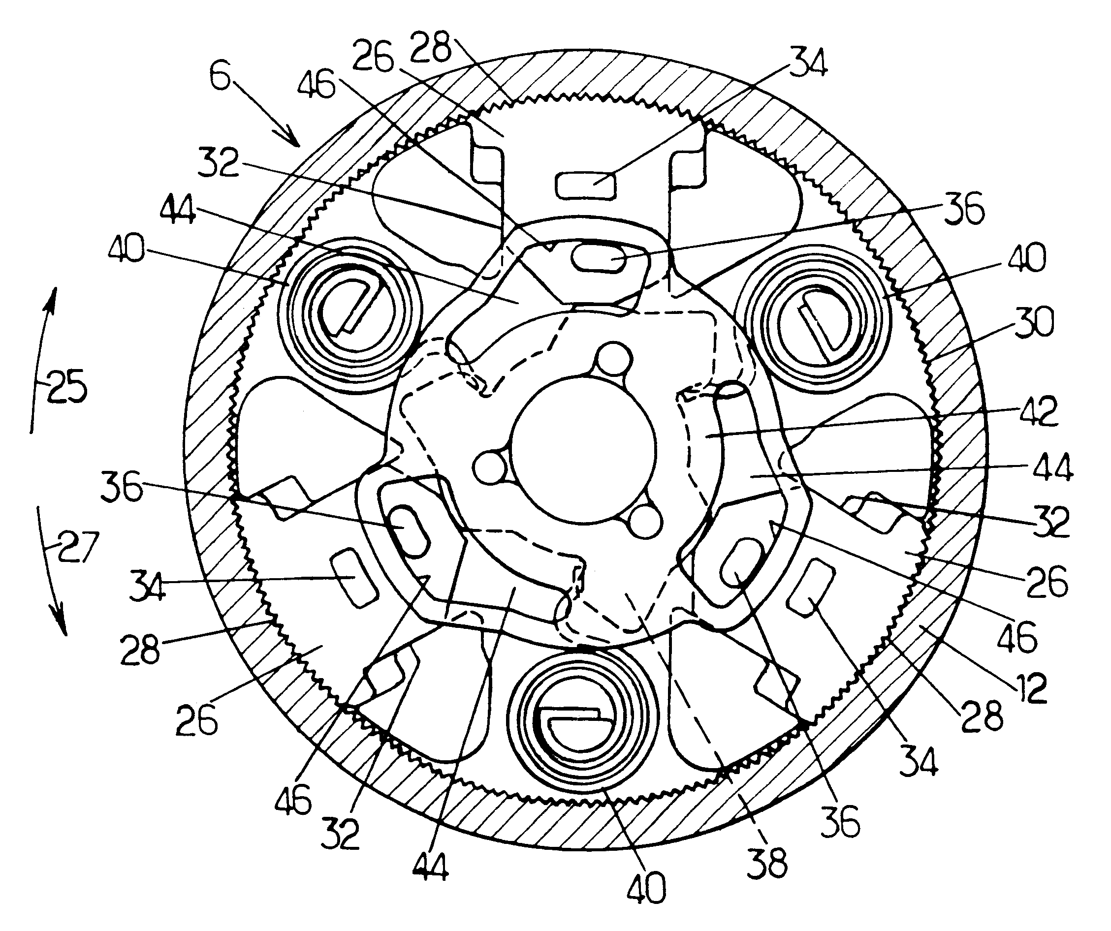
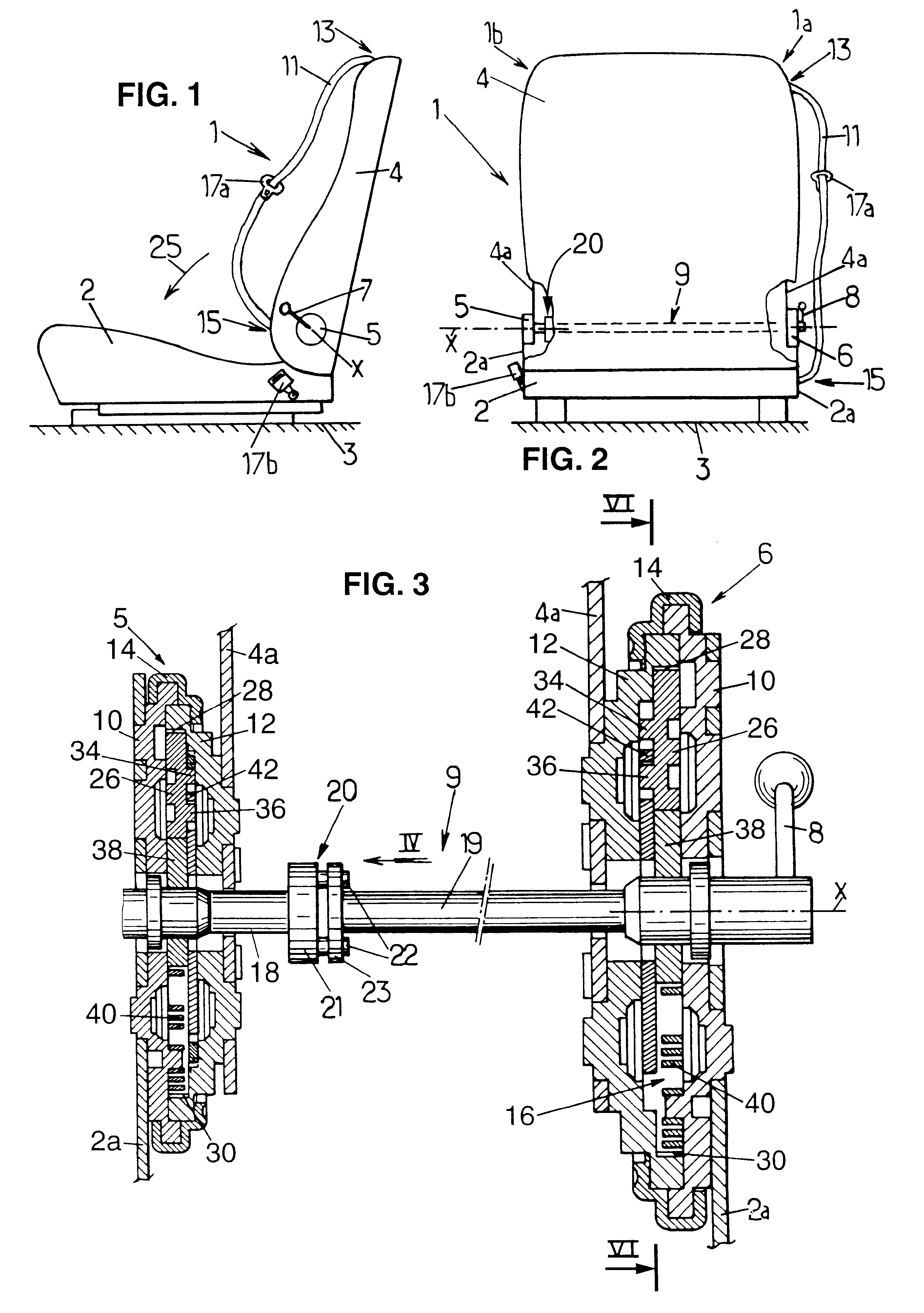
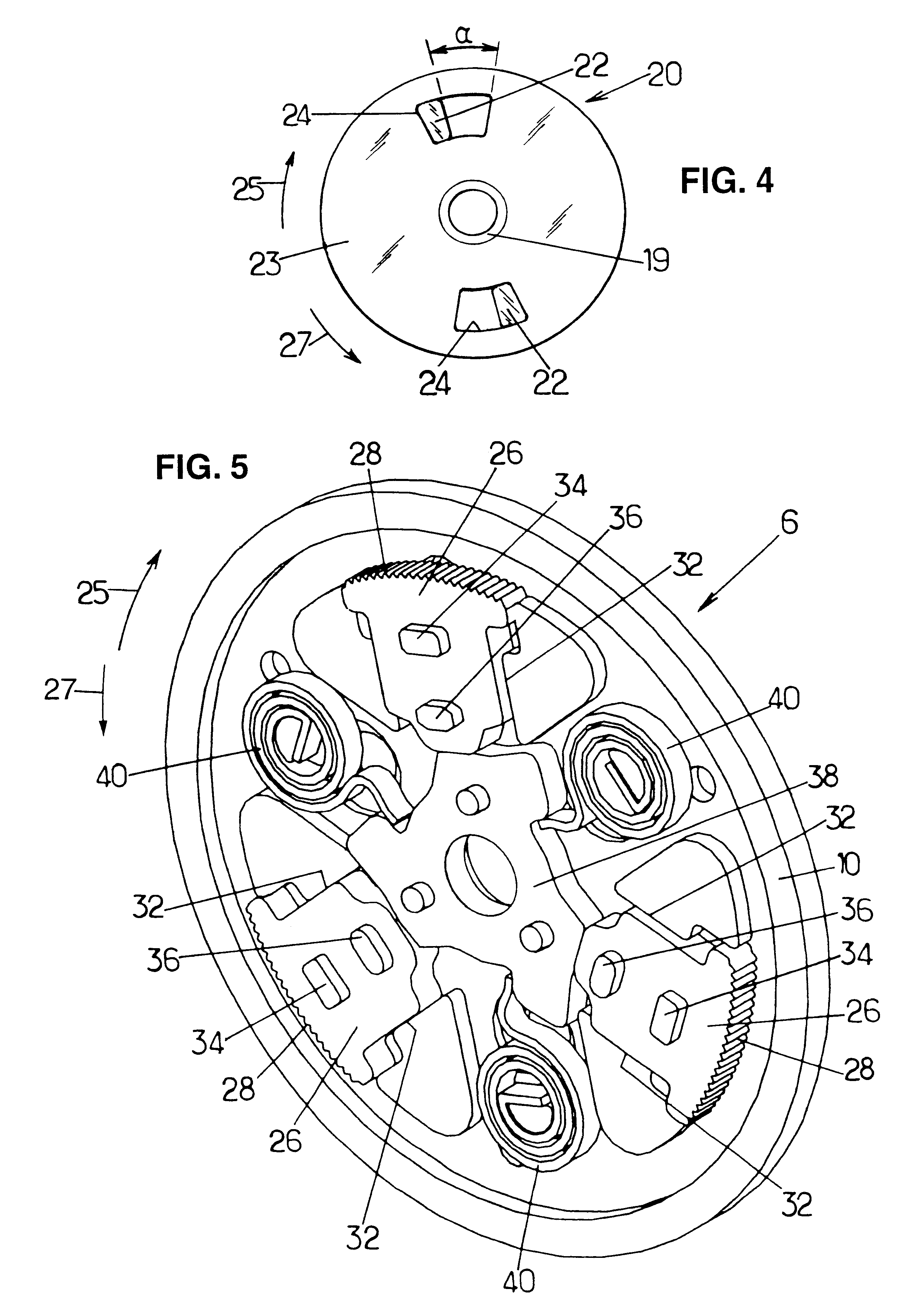
The present invention relates to a seat with two hinges that connect the seat back to the seat proper. The technical effect of the invention is to prevent the two sets of teeth of the hinges from being offset angularly in opposite directions relative to each other, which can occur when the first and second strength members engage with each other. This is achieved by shaping the second hinge so that the second set of teeth is in an intermediate position between its limit-of-engagement position and its maximally separated position when the first set of teeth is in its limit-of-engagement position. This ensures that the first set of teeth engages properly with the corresponding second set of teeth before the second set of teeth engages in its own position. Even if the second set of teeth remains offset relative to the first set of teeth, the lost motion coupling still allows the slug on the first strength member to reach its fully engaged position. The invention also includes optional provisions such as shaping the second hinge so that it travels over at least one half of its second stroke when the actuating member is moved in a first angular direction far enough for the second set of teeth to go from its limit-of-engagement position to its maximally separated position, using truncated teeth with flat free ends, and providing flats on the free ends of the truncated teeth. The seat is provided with a seat belt connected to the seat back in the vicinity of the first side of the seat, the first hinge is stronger than the second hinge, the first hinge is of diameter larger than the second hinge, the control member of each hinge is a control mask provided with at least one cam edge that comes into abutment against a stud provided on the slug so as to push the slug into its retracted position when the cam of the hinge is in the active position, and the first and second cam are the cams of the first and second hinges, respectively.

Problems solved by technology

The seat described in that document is quite satisfactory but does however suffer from the drawback that, because of the tolerances for assembling the structure of the seat, combined with the tolerances for assembling the seat to the floor of the vehicle, and also combined with a small amount of angular play in the first and second hinges, the teeth on the slugs can find themselves in angular positions that differ from one hinge to the other relative to the teeth of the corresponding first set of teeth.
In which case, the two hinges are latched only improperly after re-locking, so that the back of the seat offers only relatively weak resistance to torque that can be exerted on it about its axis of rotation.
Even if they are rare, such situations are dangerous for the user of the seat, particularly (but not exclusively) when the back of the seat carries a seat belt.

Method used


Image

  • Vehicle seat equipped with a hinge mechanism
  • Vehicle seat equipped with a hinge mechanism
  • Vehicle seat equipped with a hinge mechanism

Examples


Embodiment Construction

In the various figures, like references designate identical or similar elements.

As shown diagrammatically in FIGS. 1 and 2, the invention relates to a vehicle seat 1, in particular a front seat of a motor vehicle. The seat comprises a seat proper 2 mounted on the floor 3 of the vehicle, and a seat back 4 mounted to pivot on the seat proper 2 about a transverse horizontal axis X.

More precisely, the rigid strength member 4a of the seat back is connected to the rigid strength member 2a of the seat proper via first and second hinges 6, 5 which are situated on respective ones of the first and second sides 1a, 1b of the seat, and which are controlled by a handle 8 situated on the first side 1a of the seat. These two hinges are connected together via a coupling 9 extending horizontally and transversely relative to the seat.

In addition, in the example considered herein, the seat 1 is further provided with a seat belt 11 that is connected to the top portion of the seat back 4, and to the sea...


PUM


Abstract

A vehicle seat comprising a seat back mounted to pivot on a seat proper by means of first and second hinges, each of which is made up of two pivotally-mounted cheek plates that can be locked by slugs controlled by a rotary cam so that they are caused to come to mesh in a fixed set of teeth. The cams of the two hinges are connected together via a lost motion mechanism, and the fixed set of teeth of one of the hinges has truncated teeth, each of which forms a flat.

Description

The present invention relates to vehicle seats equipped with hinge mechanisms.More particularly, the invention relates to a vehicle seat having first and second sides, said seat comprising a seat proper and a seat back mounted to pivot relative to the seat proper by means of a hinge mechanism, said hinge mechanism comprising first and second hinges which are disposed on respective ones of the first and second sides of the seat, and each of which comprises:first and second cheek plates mounted to pivot relative to each other about an axis of rotation that is common to the first and second hinges, the first cheek plates of the first and second hinges both being secured to a first element chosen from the seat proper and the seat back, while the second cheek plates of the first and second hinges are both secured to a second element chosen from the seat proper and the seat back, the second cheek plate of each hinge being permanently secured to or integral with a first set of teeth which ...

Claims


Application Information

Patent Timeline
Patent Type & Authority Patents(United States)
IPC IPC(8): B60N2/235A47C1/024B60N2/22
CPCB60N2/2358
Inventor BALOCHE, FRAN.CEDILLA.OIS
Owner FAURECIA
Learn More