Dimmer for energy saving lamp

a technology of energy saving lamps and dimmers, which is applied in the direction of electric variable regulation, process and machine control, instruments, etc., can solve the problems of difficult dimming of fluorescent lamps, difficult circuit arrangements and topologies, and inability to adapt phase control dimmers, etc., to achieve simple circuitry and alleviate the complexity of circuitry required

Inactive Publication Date: 2004-04-27
CLIPSAL ASIA HLDG
View PDF7 Cites 36 Cited by
  • Summary
  • Abstract
  • Description
  • Claims
  • Application Information

AI Technical Summary

Benefits of technology

It is therefore an object of the present invention to provide improved circuits, devices and apparatuses for dimming a fluorescent lamp, especially a compact fluorescent lamp or an energy saving lamp. In particular, it will be an object of the present invention to provide simple dimmers for use with a compact fluorescent lamp which can be remotely located from the fluorescent lamp. It is also another object of the present invention to provide simple circuitry which can be utilized to dim a compact fluorescent lamp without the need of zero-crossing detection of the AC input line to alleviate the complicated circuitry required for such detection. Furthermore, it is an object of the present invention to provide a two-wire dimmer for a fluorescent lamp or the like. It is a least an object of the present invention to provide the public with the choice of a dimmer which can be used with a fluorescent lamp, such as compact fluorescent lamp or an energy saving lamp.

Problems solved by technology

However, dimming of fluorescent lamps has been historically difficult and requires complicated circuit arrangements and topologies.
However, in circumstances in which the detection of zero crossing is difficult, for example, in the case of a fluorescent lamp with an electronic capacitive ballast, such phase control dimmers will not be suitable.
Furthermore, because of the difficulty in dimming fluorescent lamps, most commercially available dimmable fluorescent lamps have the dimmer integrated with the ballast which means remote dimming of conventional fluorescent lamps with integrated electronic ballasts at remote switching locations such as wall-mounted switches is not possible.

Method used


Image

  • Dimmer for energy saving lamp
  • Dimmer for energy saving lamp
  • Dimmer for energy saving lamp

Examples


first embodiment

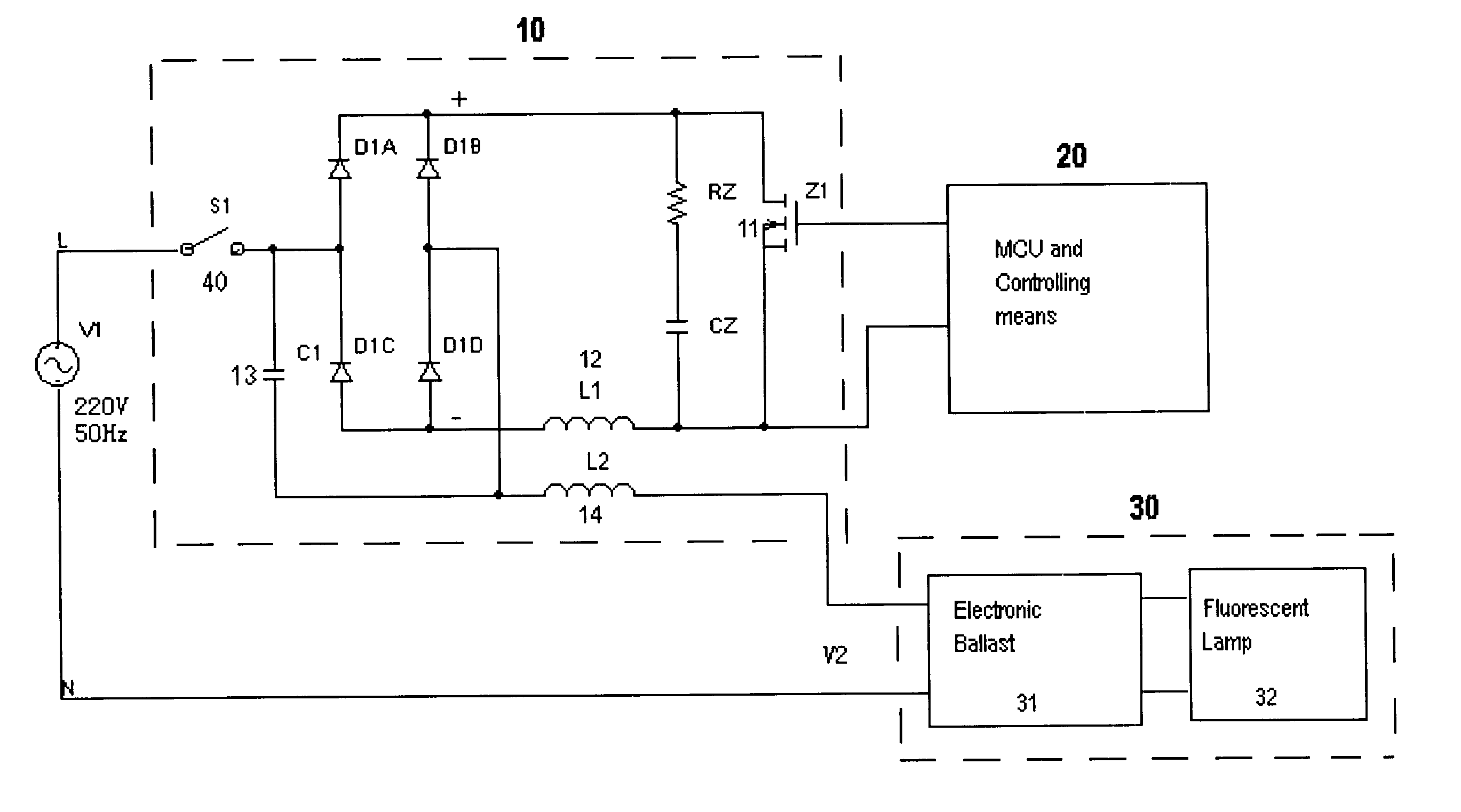
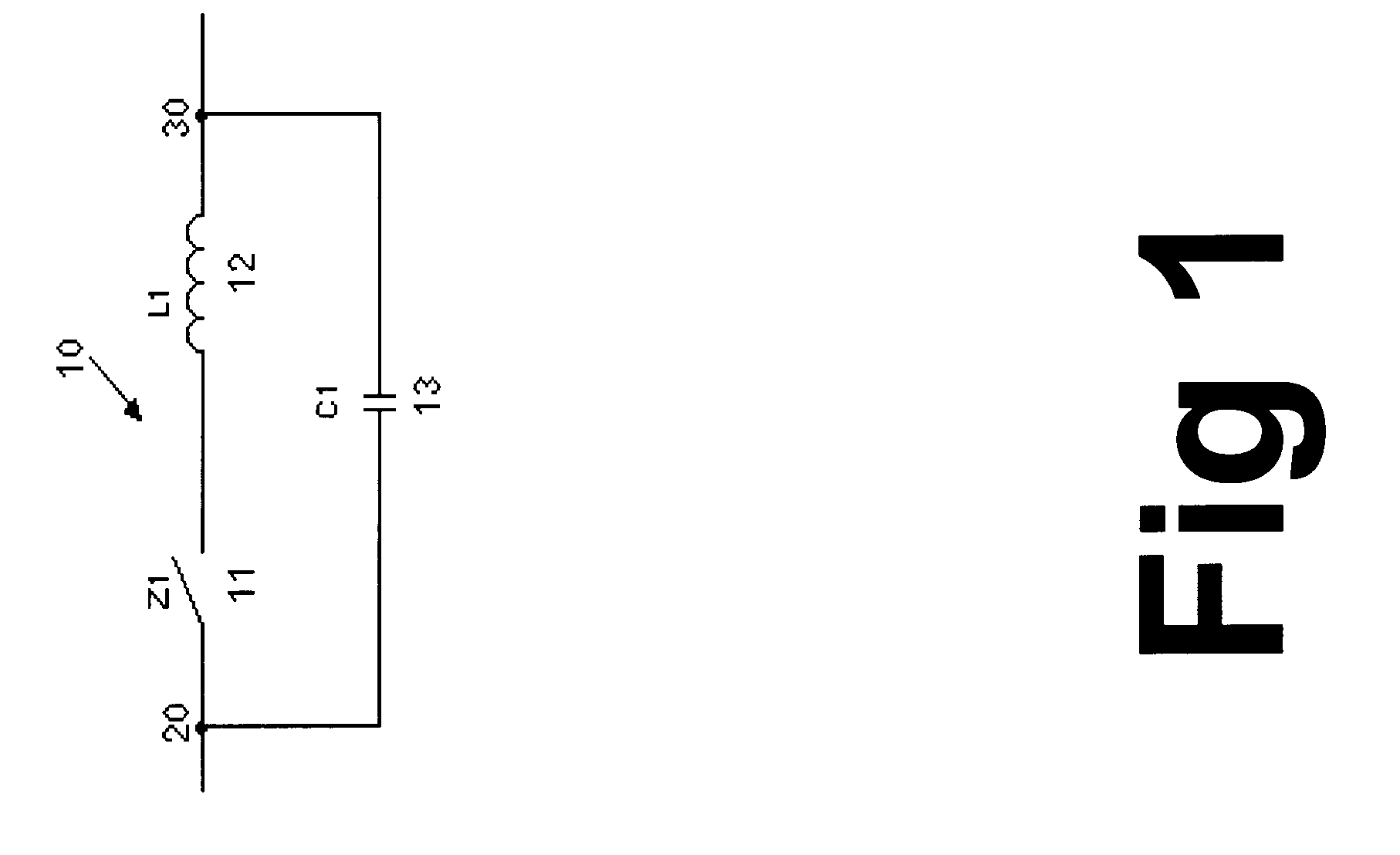
Referring to FIG. 2 in which a schematic dimming block of the present invention is shown, the dimming circuit arrangement includes the switching or switched-mode power supply building block of FIG. 1 plus an additional inductor L2 which is connected at the output node 30 of the basic building block of FIG. 1. This additional inductor L2 is intended to be connected between the output of the switching power supply and the input of the electronic ballast of a compact fluorescent lamp. The value of inductance of this additional inductor L2 (14) is largely dependent on the impedance of the capacitive electronic ballast at the operating chopping frequency and is usually larger than that of L1. The output node of the dimming block is designated with the numeral 40.

second embodiment

Referring to FIG. 3 in which the present invention is shown, a bipolar transistor Q1 (111) is inserted in the place of the switching device of FIGS. 1 and 2 as an example of a switching device and a uni-directional current limiting device, which is a diode D1 in the present case, is connected in series between the bipolar transistor 111 and the input node. This diode is added to protect the transistor from damage due to reverse biasing and may be inserted between the transistor Q1 (111) and the inductor L1 (12).

third embodiment

Referring to FIG. 4 in which the dimming circuitry of the present invention is shown, it will be noted that this circuit connection is generally identical to that of FIG. 3 except that a second pair of a bipolar transistor Q2 (112) and a diode D2 is connected in parallel across the first pair of series connection of the first transistor Q1 (111) and diode D1. It will be noted that the allowable current flowing directions in the first and second transistor diode pairs are generally opposite.

Referring to FIG. 5, a fourth embodiment of the dimming circuitry of the present invention is shown. In its embodiment, the series combination of the inductor L1 (12) and the switching device Q1 (111) as shown in FIG. 1 is embedded into a rectifying circuitry so that, when the input node of the dimming circuitry is connected to AC source, the switching device (111), which is a bipolar transistor Q1 (111) in this embodiment, is supplied with full-wave rectified power during full cycles of the AC si...


PUM


Abstract

A dimmer for a compact fluorescent lamp including a high-frequency switching circuit for generating PWM or other similar control signals and a filter with simple filtering elements. The dimmer circuitry is simple and can be built on a wall-mountable housing for retro-fitting even in an existing two-wire wall-socket.

Description

FIELD OF INVENTIONThe present invention relates to circuits, devices and apparatuses for dimming electrical lighting. More particularly, this invention relates to dimming circuits, devices and apparatuses for use with energy saving lamps or compact fluorescent lamps.BACKGROUND OF THE INVENTIONCompact fluorescent lamps, more commonly known as energy saving lamps, are widely used nowadays because of the many advantages including a high power efficiency and a long operating life.It is well known that fluorescent lamps appear as a variable or non-linear load to a power supply depending on the lamp operating modes. In order to supply an appropriate amount of current for proper lamp operation regardless of the instantaneous operating mode, a ballast is always provided between the main power supply and the fluorescent lamp. In general, a ballast must provide a required high starting voltage and current as well as limiting the current which can pass through the lamp during steady-state oper...

Claims


Application Information

Patent Timeline
Patent Type & Authority Patents(United States)
IPC IPC(8): H05B41/39H05B41/42H05B41/38H05B41/392
CPCH05B41/3921H05B41/42Y02B20/19Y02B20/00
Inventor YAO, XIAO LI
Owner CLIPSAL ASIA HLDG
Why Eureka
Try Eureka