Serial bus diagnostic port of a digital system

a digital system and diagnostic port technology, applied in the field of serial bus diagnostic port of a digital system, can solve the problems of unable to access certain internal busses for debugging purposes, and increasing the development cost of many highly integrated digital systems

Inactive Publication Date: 2004-05-04
HEWLETT PACKARD DEV CO LP
View PDF6 Cites 85 Cited by
  • Summary
  • Abstract
  • Description
  • Claims
  • Application Information

AI Technical Summary

Problems solved by technology

Digital systems are increasingly integrating more logic, particularly in the case of system-on-a-chip implementations, such that certain internal busses are no longer accessible for debug purposes.
Without access to these internal busses, not only have many highly integrated digital systems become less reliable, but also development costs of many highly integrated digital systems have increased.
As a result, legacy devices, such as a parallel port, a RS-232 port and a floppy drive, which were typically integrated in a digital system are increasingly not being offered or supported on new digital systems.
Thus, for many new digital systems, an effective way of debugging a digital system has not been available.
Further, since support of legacy devices by digital systems has varied among older digital systems and among newer digital systems, there is currently no industry standard methodology for debugging or diagnosing a digital system.
USB ports, however, have been ill-suited for software debugging in light of the software-intensive nature of a universal serial bus.
Typically, in a computer system having USB ports, a USB master controller is virtualized and embedded in an operating system, such that software debugging of the computer system has not been a viable option.
Debugging of digital systems thus has primarily or strictly been limited to the integrated legacy devices described above.

Method used


Image

  • Serial bus diagnostic port of a digital system
  • Serial bus diagnostic port of a digital system
  • Serial bus diagnostic port of a digital system

Examples


Embodiment Construction

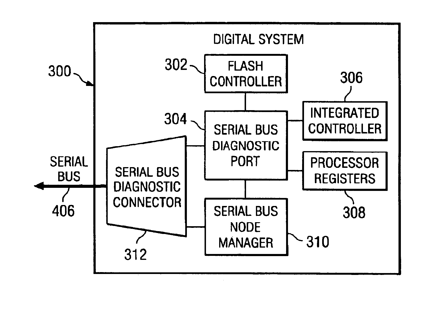
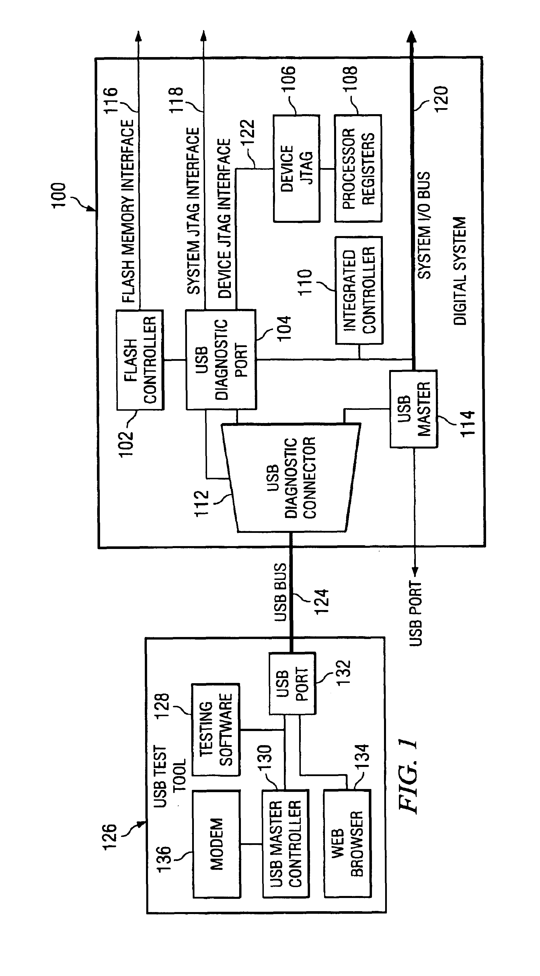
Turning now to the drawings, FIG. 1 shows an exemplary universal serial bus (USB) diagnostic system environment providing a USB test or diagnostic tool 126 coupled or interfaced to a digital system 100. The USB test tool 126 is shown including a USB port 132 coupled to testing software 128, a USB master controller 130 and a web browser 134. The USB master controller 130 is further coupled to a modem 136. The USB test tool 126 can employ the testing software 128 to test the digital system 100 via communication through a USB diagnostic port 104 in the digital system 100. Via the modem 136, testing software 128 can be downloaded to the USB test tool 126. The web browser 134 may provide a graphical user interface for the testing software 128. The USB test tool 126 can essentially be any digital system with a USB master controller 130. For example, the USB test tool 126 can be a portable or handheld computer containing the USB master controller 130. The USB test tool 126 can be configure...


PUM


Abstract

A digital system provides a serial bus diagnostic port such as, for example, a universal serial bus (USB) diagnostic port. The USB diagnostic port can include a USB slave device operable to interface to a universal serial bus, a flash memory controller interface coupled to the USB slave device and operable to interface to a flash memory controller, and a test access port controller coupled to the USB slave device and operable to interface to a test access port. The diagnostic port can further include a system interface coupled to the USB slave device and operable to interface to an integrated controller independently of an operating system. Via the diagnostic port, a USB testing tool with testing software can access and debug internal logic of the digital system. As an alternative to a USB diagnostic port, the serial bus diagnostic port can be implemented in a variety of wired or wireless implementations such as, for example, an I.E.E.E. 1394 diagnostic port, an Ethernet diagnostic port, or a wireless Internet diagnostic port. Further, the serial bus diagnostic port can, for example, be used for software development, in-factory testing or in-field diagnostics of the digital system.

Description

1. Field of the InventionThe present invention relates to a serial bus diagnostic port of a digital system.2. Description of the Related ArtWith the growing proliferation of digital systems, which for example include computers, digital televisions, digital camcorders, satellite receivers, digital cameras, digital video or versatile disc (DVD) players, digital cell phones, digital video cassette recorders, digital scanners, game players, set-top boxes, digital monitors, personal digital assistants and to MP3 players, debugging of digital systems is becoming a paramount concern. Debugging of digital systems has typically involved use of integrated legacy devices such as a parallel port, a RS-232 or compatible port, or a floppy drive. For example, debugging of a computer system can entail use of a parallel port, RS-232 port, or a floppy drive. A parallel port has commonly been used to program flash memory in a portable computer system using a Super I / O chip. A RS-232 or EIA232 port, a ...

Claims


Application Information

Patent Timeline
Patent Type & Authority Patents(United States)
IPC IPC(8): H02H3/05G06F11/267
CPCG06F11/267
Inventor LANDRY, JOHN A.DIEHL, WILLIAM W.
Owner HEWLETT PACKARD DEV CO LP
Why Eureka
Try Eureka