
Magazine for bullet pneumatic arms and case for said bullet magazine of a pneumatic arm

a pneumatic arm and bullet magazine technology, applied in the direction of ammunition loading, white arms/cold weapons, weapon components, etc., can solve the problems of low reliability of such a firearm, limited the possibility of shooting from such a firearm, and small capacity, and achieve the effect of convenient in service and easy manufacturing

Inactive Publication Date: 2004-05-18
ZAKRYTOE AKTSIONERNOE OBSHCHESTVO GRP ANICS
View PDF18 Cites 28 Cited by
  • Summary
  • Abstract
  • Description
  • Claims
  • Application Information

AI Technical Summary

Benefits of technology

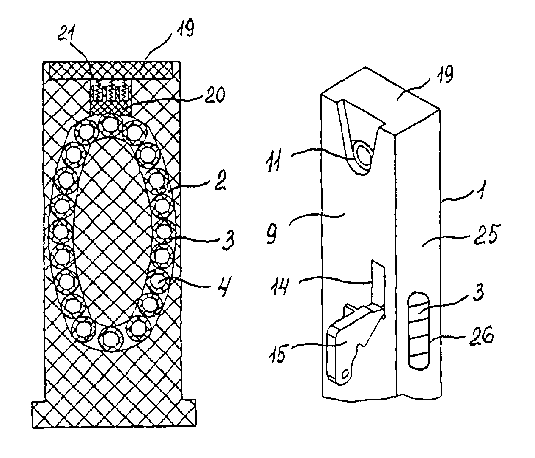
The herein-proposed technical solutions are based on the idea of providing a magazine for a pneumatic firearm shooting bullets of an arbitrary form, which magazine will be structurally simple, easy to manufacture, convenient in service, in which magazine bullets are preliminarily loaded into containers, and these containers are arranged in a closed passage and move therealong, each loaded container being sequentially delivered to the shooting line for shooting.
improve the reliability of feeding bullets for shooting, and thus to improve the reliability of the firearm itself;
increase the magazine capacity owing to the presence of a closed passage practically of an arbitrary form and length;
eliminate deformation of bullets in the magazine, whereby ballistic characteristics of the firearm are improved.
Installed in the magazine casing between an upper wall of the casing and the closed passage is a block which contacts the containers and provides stable sequential positioning of each loaded container coaxially with the bullet passage of the firearm barrel before the shot. The wall of the block viewed from the side of the closed passage has a form repeating the form of the external wall of the passage, when the containers move along the passage. In the block wall from the side of the closed passage a cutout is provided, whose form repeats the form of the generatrix of the external side wall of the container. Between the wall of the casing and the block at least one spring is installed, which urges the block away from the wall of the casing in such a manner that during each movement of the containers along the closed passage the lower side of the block becomes a natural continuation of the side wall of the passage, and as the next in turn loaded container is brought to the shooting line the block descends onto the container for fixing the position of the container before the shot.

Problems solved by technology

Though the capacity of the magazine is large, the absence of forced feeding the bullets from the bin into the barrel makes the reliability of such a firearm low and limits the possibility of shooting from such a firearm, for instance, when its barrel is directed downwards.
Disadvantages of such magazines are their small capacity, as well as low reliability because of possible dropout of the bullets from the magazine as the latter is installed into or withdrawn from the firearm.
This structure is disadvantageous in a limited capacity of the magazine and long process of magazine reloading.
This structure is disadvantageous in a limited capacity of the magazine.
The main disadvantage of this structure is inadequate reliability of feeding bullets into the barrel of the firearm.
Besides, all the above magazine structures suffer from common disadvantages:
bullets in these magazines are subject to deformations associated with the mechanical mutual interaction of the bullets and with the direct action thereon of parts of the magazine and firearm, whereby the ballistic characteristics of the bullets and of the firearm are impaired.

Method used


Image

  • Magazine for bullet pneumatic arms and case for said bullet magazine of a pneumatic arm
  • Magazine for bullet pneumatic arms and case for said bullet magazine of a pneumatic arm
  • Magazine for bullet pneumatic arms and case for said bullet magazine of a pneumatic arm

Examples


Embodiment Construction

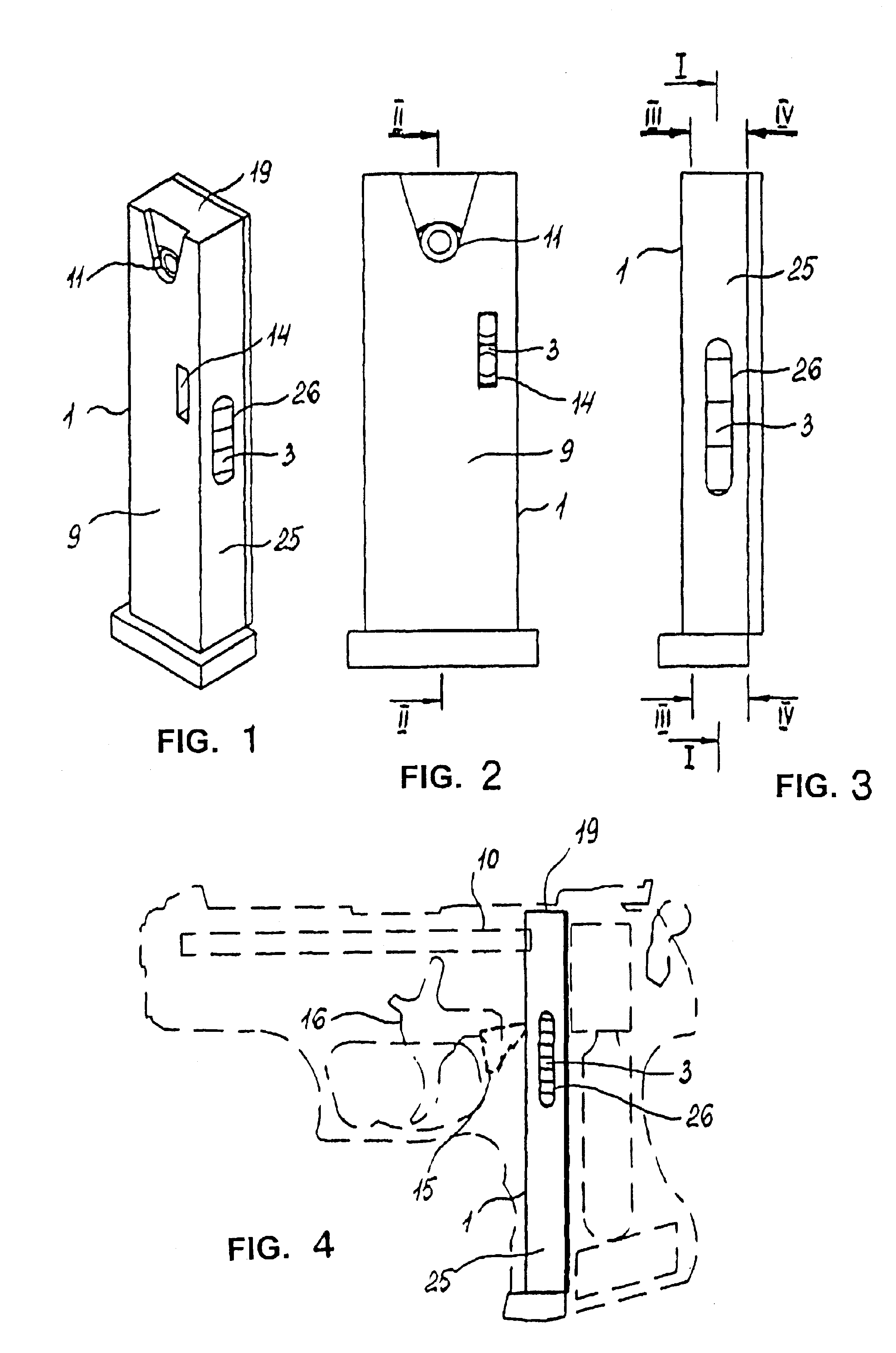
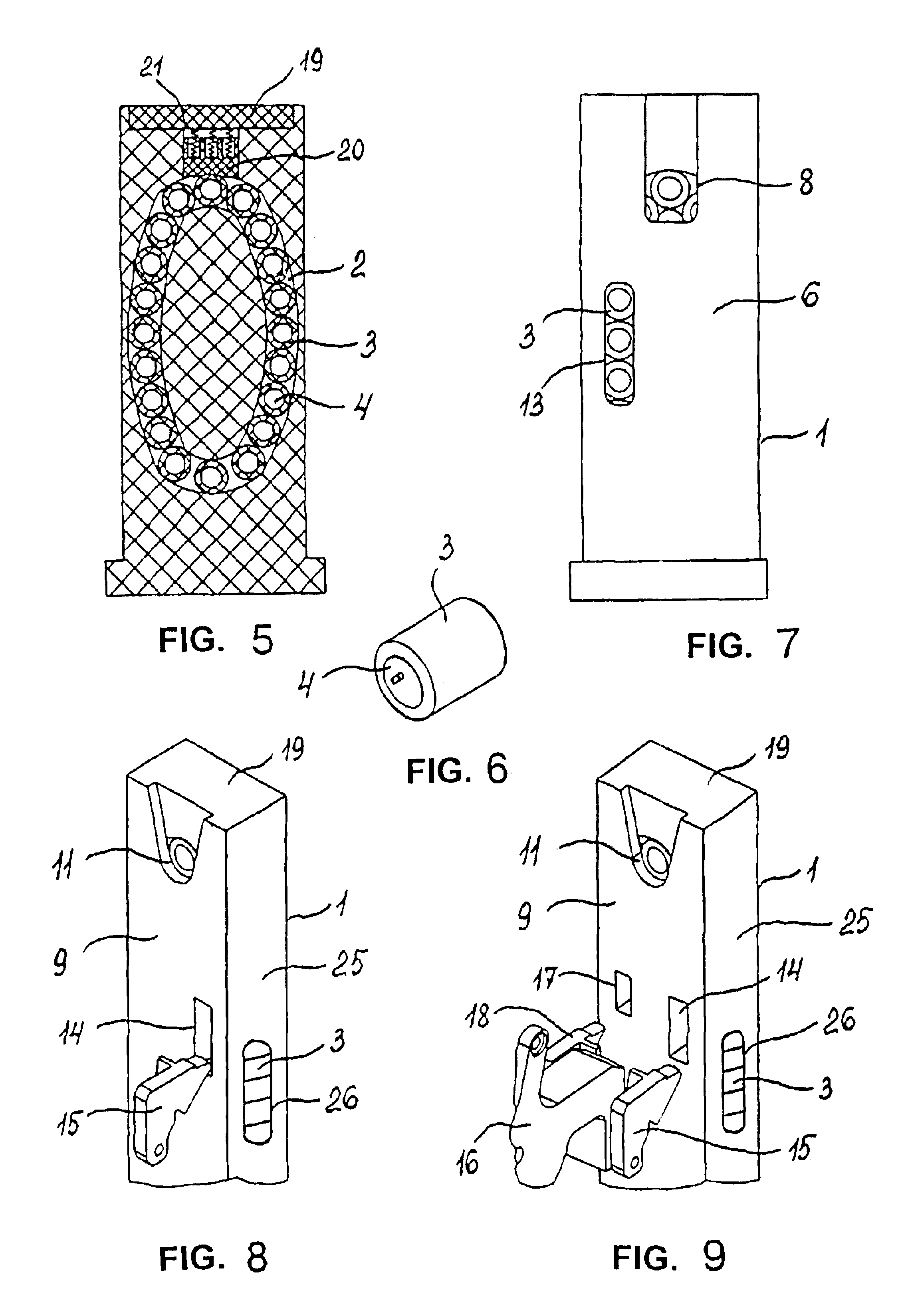
A magazine (FIGS. 1-3) for a bullet-shooting pneumatic firearm, to be disposed, for instance, in a firearm grip (FIG. 4), comprises a casing 1. A closed passage 2 is disposed in the casing 1 (FIG. 5). Containers 3 are arranged in the passage 2 one after another in a chain-like manner (FIG. 6), each container having a through opening 4 for loading the container with a bullet 5.

In a wall 6 of the casing 1, as viewed from the side of a passage 7 from which a portion of gas comes into the container 3 at the moment of a shot, there is a port 8 (FIG. 7). In a wall 9 of the casing 1, which is opposite the port 8, as viewed from the side of a firearm barrel 10, there is a bullet opening 11 through which under the pressure of a portion of gas a bullet 5 during the shot gets from the container 3 into a bullet passage 12 of the firearm 10. The port 8 and the opening 11 are disposed coaxially with the through opening 4 of the container 3, when a next container 3 loaded with bullet 5 occupies a ...


PUM


Abstract

A magazine for a bullet-shooting pneumatic firearm comprises a casing 1. Inside the casing 1 a closed passage 2 is provided, equipped with containers 3 with bullets 5. The magazine has a bullet opening 11 in a wall 9 of the casing 1, through which the bullet 5 during the shot, under the action of a portion of gas, gets from the container 3 into a bullet passage 12 of a barrel 10 of the firearm. The opening 11 is disposed coaxially with the bullet passage 12 of the barrel 10 of the firearm and with a through opening 4 of the container 3 occupying such position before each shot. In the wall 9 of the casing 1 above the closed passage 2 above the through opening 4 of the containers 3 a port 14 is provided for receiving an external arm 15 of a striker-and-trigger mechanism 16, under the action of which the containers 3 move along the closed passage 2, each container 3 being positioned sequentially to the shooting line. In a side wall 25 of the body 1 a longitudinal opening 26 is provided for the containers to be moved with the shooter's finger when the containers are loaded with bullets 5. 14 claims, 17 illustrations.

Description

The present invention relates to compressed gas operated firearms and more particularly to multiple-charge magazines for pneumatic gas-cylinder operated firearms shooting bullets, and also to containers for bullets, used in magazines of such firearms.STATE OF THE ARTKnown in the art are designs of magazines employed in pneumatic firearms using compressed gas cylinders and shooting, for instance, spherical bullets.Bin-type magazines are known (U.S. Pat. Nos. 3,077,875, C1. 124-76, 1963 and U.S. Pat. No. 4,147,152, C1. F41B 11 / 06, priority of 03.01.1977), wherein bullets are loaded into a cavity present in the pistol itself, and the bullets are passed for shooting into the barrel by gravity. Though the capacity of the magazine is large, the absence of forced feeding the bullets from the bin into the barrel makes the reliability of such a firearm low and limits the possibility of shooting from such a firearm, for instance, when its barrel is directed downwards.Magazines are known, whic...

Claims


Application Information

Patent Timeline
Patent Type & Authority Patents(United States)
IPC IPC(8): F41B11/00F41B11/02F41A9/61F41B11/55
CPCF41B11/55
Inventor PETROSYAN, ALEKSEI LVOVICHSHIPACHEV, ALEKSEI BORISOVICH
Owner ZAKRYTOE AKTSIONERNOE OBSHCHESTVO GRP ANICS
Learn More