Vehicle engine cooling system without a fan

a technology for cooling systems and engines, applied in the direction of machines/engines, mechanical equipment, transportation and packaging, etc., can solve the problem of limited remote location to very few places

Inactive Publication Date: 2004-05-25
INT TRUCK & ENGINE CORP CANADA
View PDF18 Cites 44 Cited by
  • Summary
  • Abstract
  • Description
  • Claims
  • Application Information

AI Technical Summary

Benefits of technology

FIG. 1 is a simple one line drawing of a vehicle with a fan-less cooling system for a mobile vehicle installed and made in accordance with this invention.

Problems solved by technology

This requirement of air (free of debris etc) along with a rotating fan has limited the remote location to very few places.

Method used


Image

  • Vehicle engine cooling system without a fan
  • Vehicle engine cooling system without a fan
  • Vehicle engine cooling system without a fan

Examples


Embodiment Construction

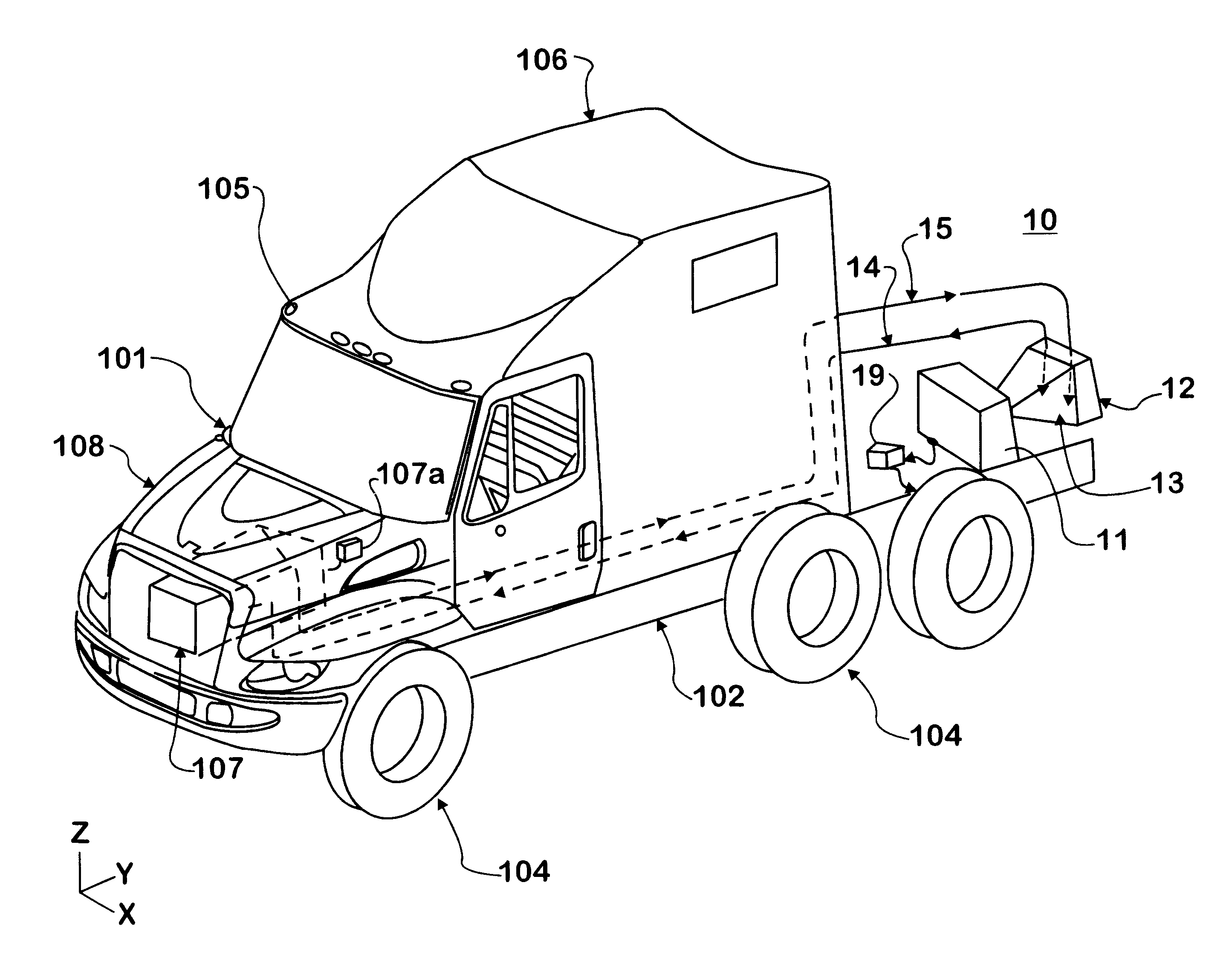
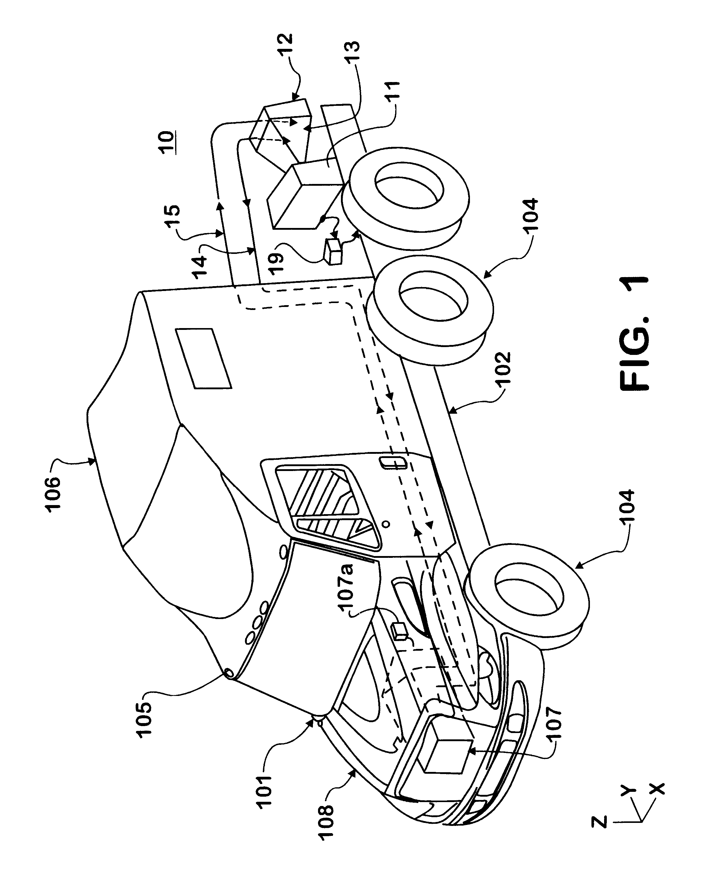
FIG. 1 shows a vehicle 101 containing a fan-less cooling system 10 made in accordance with this invention. The vehicle 101 has a chassis 102 engaged to axles with wheels 104. There is a driver cab 105 engaged to the chassis 102. Heavy-duty highway vehicle cabs 105 may contain a sleeper compartment 106. There is an engine 107 engaged to the chassis 102 under a hood 108, the engine 107 for providing motive force to the vehicle 101. The engine 107 may have auxiliary systems such as an internal oil system and an engine coolant system. The internal oil system and the engine coolant system of the engine 107 may be cooled by a fan-less cooling system 10 made in accordance with this invention. The fan-less cooling system may be used alone to cool these engine auxiliary systems are in conjunction with a conventional ram air engine cooling arrangement. The cab 105 and sleeper 106, if provided, may have an air conditioning system consisting at a minimum of a fan to disperse air blown across co...


PUM


Abstract

A vehicle cooling system for a mobile vehicle consists of three essential parts. These are a compressed air reservoir, a heat exchanger and a duct connecting the reservoir and the heat exchanger. On demand, the compressed air will be released to the duct and will expand (as the end connected to the reservoir is expected to be lower in cross-sectional area compared to the end connected to the face of the heat exchanger). This expansion will lead to the reduction in air temperature. This helps in increasing the heat rejection capacity of the cooling system. The colder air passes through the heat exchanger and carries away the heat. This air exits from the other end of the heat exchanger into the environment. A fan is optional to operate behind the heat exchanger to help draw the air though it. The compressed air may originate in the vehicle air system for operating air brakes found on medium and heavy-duty trucks or the compressed air may originate from a separate air compressor. The system may be located in various locations on the vehicle due to the lack of reliance on ram air caused from vehicle movement.

Description

This invention relates to a cooling system for a mobile vehicle that may operate without the use of a fan. Specifically, the fan-less cooling system will provide cooling to engine coolant coils by releasing high-pressure air to expand around the outside of the tubing for engine coolant. The expansion of the pressurized air will chill the air. The air will absorb heat from the engine coolant in the tubing. A fan may be used to accelerate the expansion however no fan is required. The fan-less cooling system does not need to be installed at the front of the mobile vehicle as ram air from vehicle movement will not be necessary to provide driving force for the gas expansion.PRIOR ARTVehicles have traditionally drawn cooling air or ram air from a location towards the front of a vehicle. The vehicle's movement along the road provides the force to drive air across cooling coils of the engine or other vehicle heat exchangers such as interior air conditioning or transmission oil coolers. Obvi...

Claims


Application Information

Patent Timeline
Patent Type & Authority Patents(United States)
IPC IPC(8): B60K11/00F01P5/02F01P11/10
CPCB60K11/00F01P5/02F01P11/10Y10S180/903
Inventor JAIN, SUNIL K.NOBEL, TIM P.WOOLDRIDGE, SCOTT A.BEIGEL, DAVID J.
Owner INT TRUCK & ENGINE CORP CANADA
Why Eureka
Try Eureka