Brake effort monitor

a technology of effort monitor and brake shoe, which is applied in the direction of dynamo-electric converter control, motor/generator/converter stopper, braking system, etc., can solve the problems of increased operation cost, wear of brake shoes or pads, and increased energy consumption, so as to maximize the use of dynamic braking and save costs over tim

Inactive Publication Date: 2004-05-25
WESTINGHOUSE AIR BRAKE TECH CORP
View PDF3 Cites 35 Cited by
  • Summary
  • Abstract
  • Description
  • Claims
  • Application Information

AI Technical Summary

Benefits of technology

Still another object of the present invention is to provide a brake effort monitor which uses a software logic

Problems solved by technology

On the other hand, friction braking causes wear of the brake shoes or pads and also requires energy to produce the air or hydraulic pressure required to generate the braking forces.
Therefore, when dynamic brake is not fully utilized, operation costs increase.
If the combined brake system is not performing as designed, the resultant wear in over friction braking can be costly.
Under braking of the dyn

Method used


Image

  • Brake effort monitor
  • Brake effort monitor
  • Brake effort monitor

Examples


Embodiment Construction

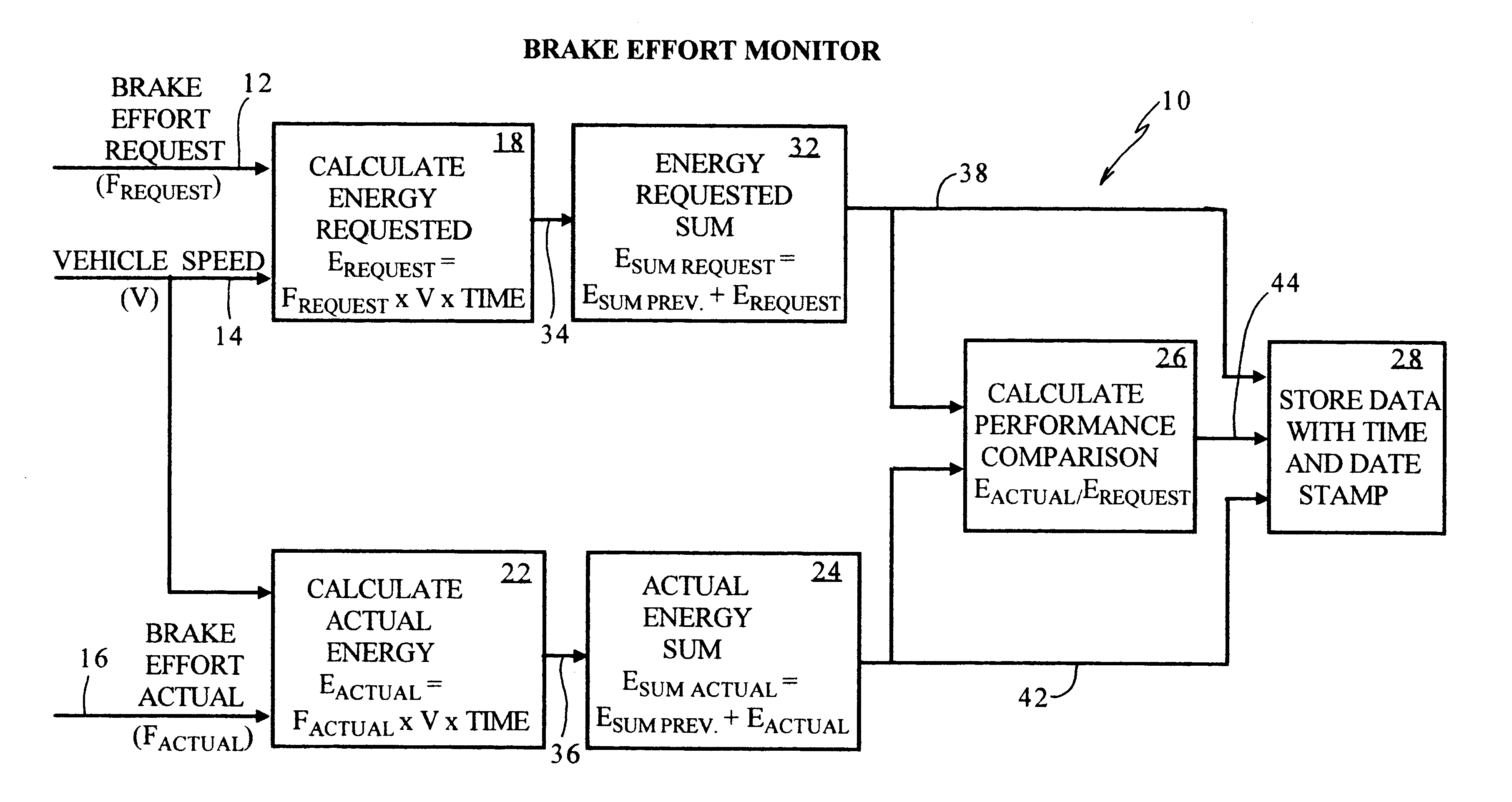
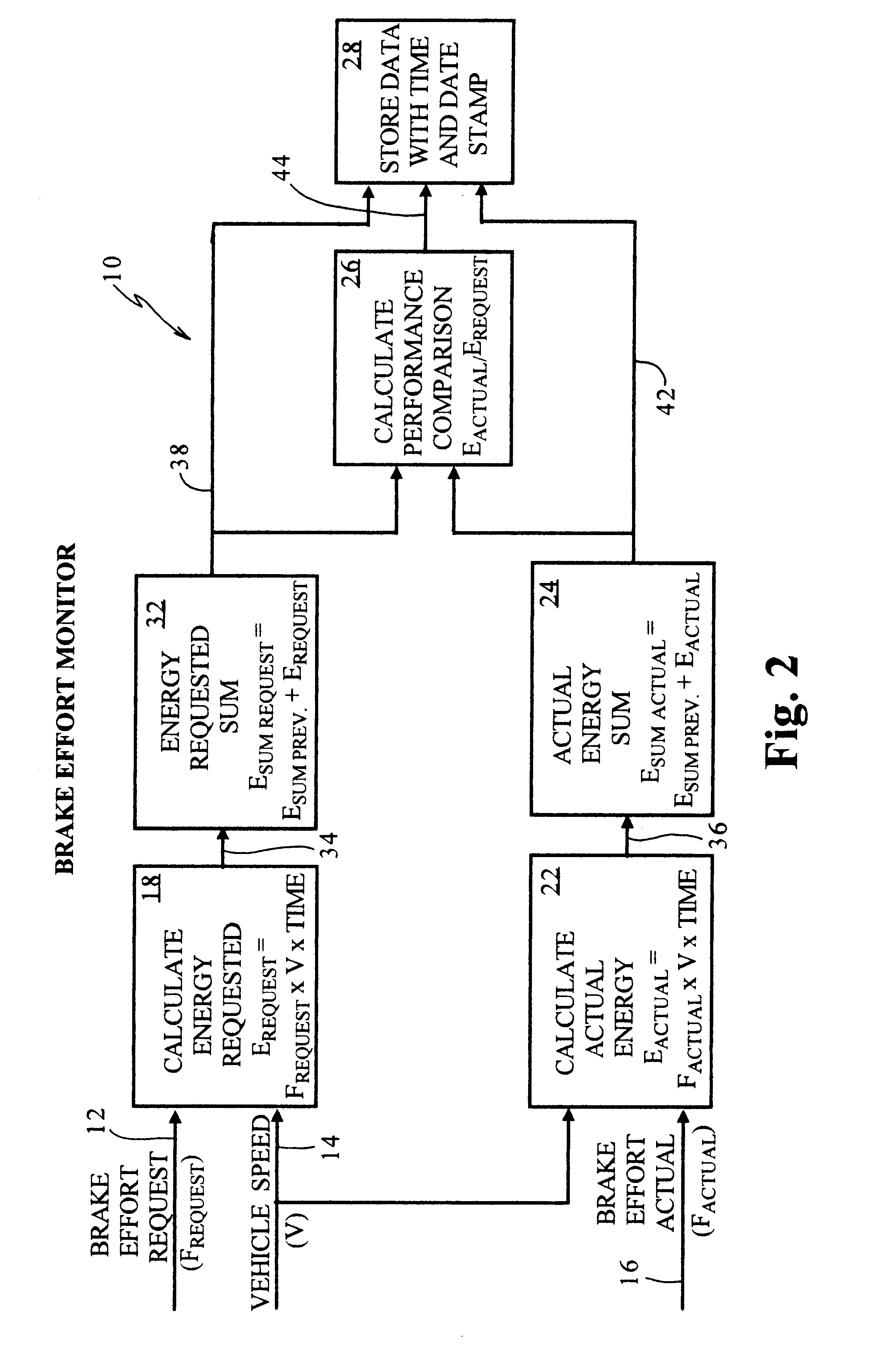
Referring initially to FIG. 2 there is illustrated a presently preferred embodiment of a brake effort monitoring apparatus constructed according to the present invention generally indicated by reference numeral 10. In order for the brake effort monitor 10 to operate as intended it requires a brake effort required signal 12, a vehicle speed signal 14, and a brake effort actual signal 16 to be provided by any convenient source (not shown).

In a presently preferred configuration, the brake effort monitor communicates the vehicle speed signal 14 to at least one of a means 18 for calculating energy requested and a means 22 for calculating actual energy. The brake effort request signal 12 is communicated to a means 18 for calculating energy requested. An energy requested signal 34 is calculated using the vehicle speed signal 14 and the brake effort requested signal 12 communicated and a predetermined time period. This signal 34 is calculated by multiplying the brake effort requested signal...


PUM


Abstract

A brake effort monitor for railcar braking systems includes means connected to receive a brake effort request signal and a vehicle speed signal for generating an energy requested signal. Another device is connected to receive a brake effort actual signal and a vehicle speed signal for generating an actual energy signal. There is a mechanism connected to receive the energy requested signal and add it to one of a previous energy requested signal and a predetermined value for generating an energy requested sum signal. A device is connected to receive the actual energy signal and add it to one of a previous actual energy signal and a predetermined value for generating an actual energy sum signal. A comparator is connected to receive the energy requested sum signal and the actual energy sum signal for generating a performance comparison signal and a storage device is connected to receive at least one of an energy requested sum signal and an actual energy sum signal and a performance comparison signal for storing at least one signal.

Description

The present invention generally relates to a brake effort monitor software logic program in a microprocessor system. More particularly, the invention relates to a brake effort monitor software logic program in a microprocessor system designed to maximize dynamic brake effort and evaluate dynamic and friction braking systems for optimal braking performance in a transit vehicle and the total blended brake monitoring optimization of dynamic and friction brake systems.There is presently known in the prior art, typically on transit vehicles, the use of a combination of dynamic braking and friction braking to bring the transit vehicle to a stop. It is advantageous to use dynamic braking preferentially over friction braking because dynamic braking is "free" or actually saves money. The reason being is that there are no wearing parts involved with dynamic braking and when regenerative brake is used, which is basically electricity generated by the vehicle that can be used by other vehicles, ...

Claims


Application Information

Patent Timeline
IPC IPC(8): B60T13/58B60T17/22B60T13/10B60T13/00B60T17/18
CPCB60T13/00B60T13/586B60T17/22
Inventor SCHARPF, ROBERT N.SCHWEIKERT, DAVID E.DEWBERRY, JAMES T.
Owner WESTINGHOUSE AIR BRAKE TECH CORP
Why Eureka
Try Eureka