Drive system

a technology of driving system and drive shaft, which is applied in the direction of shock absorption device, gearing, hoisting equipment, etc., can solve the problems of reducing the life excessive load of the transmission or transfer element, and inability to damp vibrations over a wide range of frequencies,

Inactive Publication Date: 2004-06-01
ZF FRIEDRICHSHAFEN AG
View PDF16 Cites 27 Cited by
  • Summary
  • Abstract
  • Description
  • Claims
  • Application Information

AI Technical Summary

Benefits of technology

As a result of the present invention, a degree of system integration is achieved in which, through the intermeshing of the various system areas, namely, the system area comprising the vibration-damping device and the system area comprising the secondary drive system, various components can assume a double function. This simplifies the design and reduces the size of the machinery, and at the same time it allows the vibrations to be reduced precisely in the area where vibrational excitations are especially critical.
In an alternative design, it can be provided that the auxiliary drive wheel is a pulley, which has a belt-guiding section on at least one of its axial sides, and that at least one belt-guiding section comprises at least a part of the vibration-damping device. In a variant such as this, the functional or structural system integration or fusion can be achieved easily by providing at least one cover element, which covers a space in which the minimum of one deflection mass is held, on the deflection mass carrier and by designing the minimum of one belt-guiding section to comprise the minimum of one cover element. To provide reliable guidance for the belt which passes over the pulley, it is proposed that two cover elements be provided on the deflection mass carrier and that the two cover elements form two belt-guiding sections.

Problems solved by technology

Because, for cost reasons, auxiliary units of this type are usually lighter in weight than the internal combustion engine itself or represent comparatively sensitive systems, the rotational irregularities transmitted to them can cause damage to them or lead to a decrease in their life-span, especially in cases where the connection between the systems is comparatively stiff.
The transmission or transfer elements, i.e. V-belts, can also be excessively loaded.
It is not possible for such elastic coupling to damp vibrations over a wide range of frequencies.

Method used


Image

  • Drive system
  • Drive system
  • Drive system

Examples


Embodiment Construction

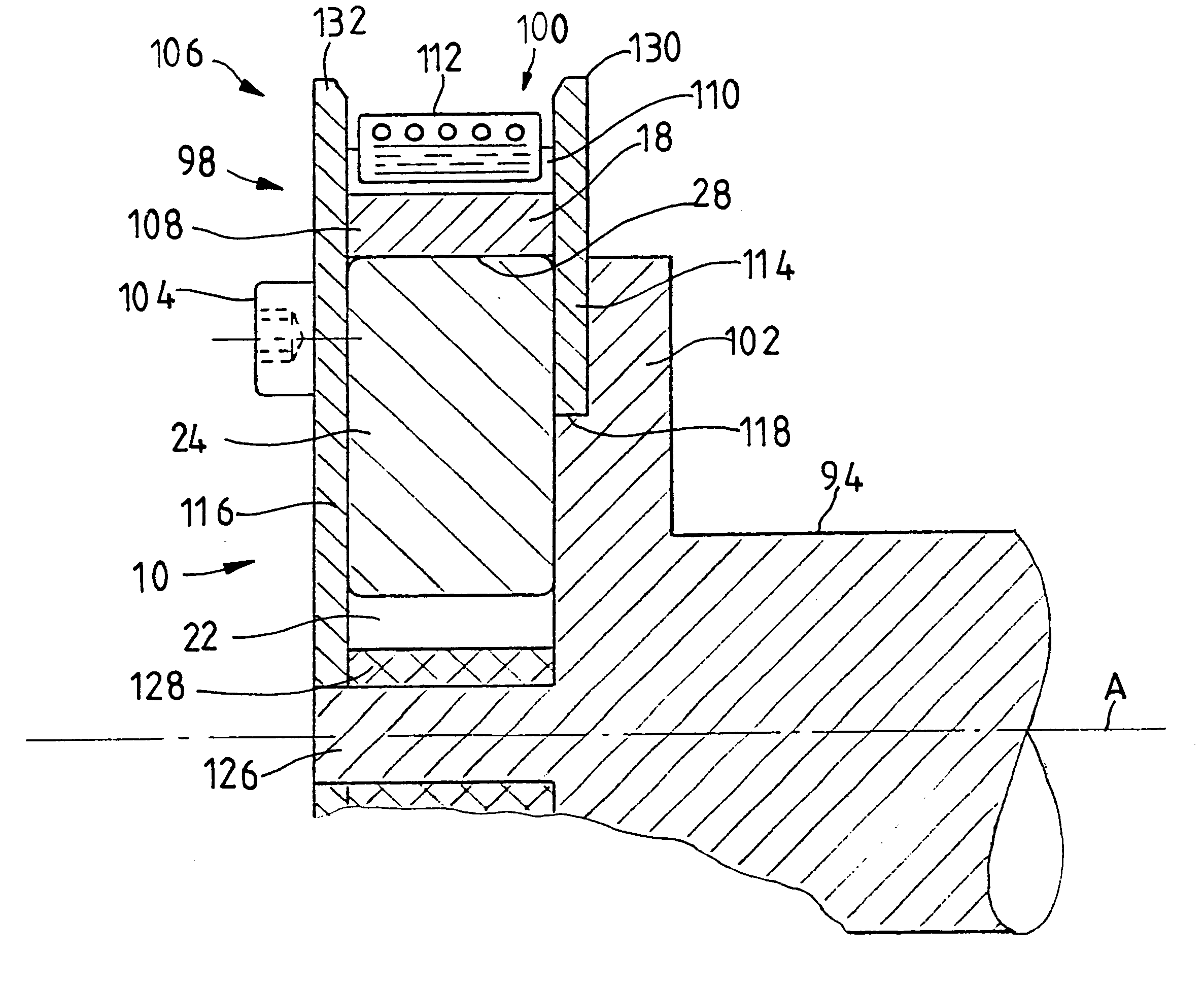
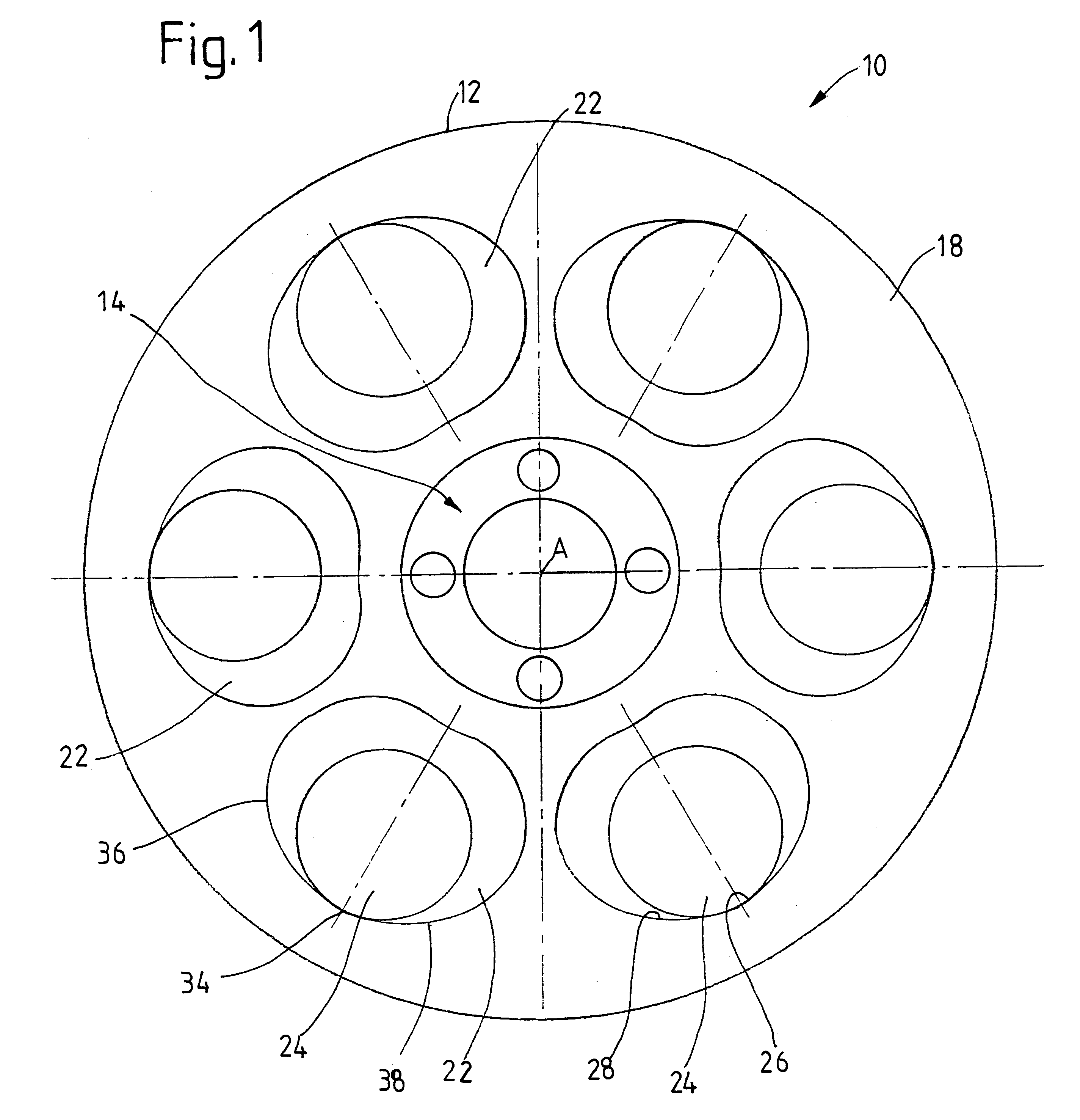
Referring to FIG. 1, there is illustrated a vibration-damping having several deflection masses moving along deflection paths. The vibration-damping device 10 comprises a deflection mass carrier 12 having a radially inner area 14 which can be connected to a shaft for rotation around rotational axis A. Several free spaces 22, distributed in the circumferential direction around the rotational axis A, are provided in a body part 18 of the deflection mass carrier 12 where each free space 22 is adapted to accept one deflection mass 24. The surface area 26 of the body part 18 forming the outside radial boundary of the free space 22 forms a deflection path 28 for the deflection mass 24 held in the associated free space 22. The axial dimension of the free spaces 22 can be substantially the same as the thickness of the disk-like or cylindrical deflection mass 24.

As illustrated in FIG. 1, the deflection paths 28 are designed to provide a summit area 34, which is the area of the deflection path...


PUM


Abstract

A drive system that includes a drive shaft, which is or can be brought into torque-transmitting connection with a drive train, a secondary drive system for transmitting torque between the drive shaft and at least one auxiliary unit, and at least one vibration-damping device including a deflection mass carrier with freedom to rotate around a rotational axis and at least one deflection mass, which can shift position relative to the deflection mass carrier in at least one deflection plane. Upon deflection of the at least one deflection mass from the home position relative to the deflection mass carrier, the radial position of the deflection mass changes relative to the rotational axis. At least part of the vibration-damping device can be integrated into part of the secondary drive system.

Description

1. Field of the InventionThe present invention pertains to a drive system, comprising a drive shaft, which is or can be brought into torque-transmitting connection with a drive train, and a secondary drive system for transmitting torque between the drive shaft and at least one auxiliary unit. The drive system also includes at least one vibration damping device, which itself comprises a deflection mass carrier with freedom to rotate around a rotational axis and at least one deflection mass, which can shift position relative to the deflection mass carrier in at least one deflection plane. Upon the deflection of the minimum of one deflection mass from a home position with respect to the deflection mass carrier, the radial position of the minimum of one deflection mass changes with respect to the rotational axis.2. Description of the Related ArtIn drive systems of this type, various devices can be used as auxiliary units, including the compressors of air-conditioning systems, cooling fa...

Claims


Application Information

Patent Timeline
Patent Type & Authority Patents(United States)
IPC IPC(8): F16F15/10F16F15/14F16F15/30F16F15/31
CPCF16F15/145F16F15/31Y10T464/50Y10T74/2128F16F15/10
Inventor FELDHAUS, REINHARDWETH, JURGENPEINEMANN, BERND
Owner ZF FRIEDRICHSHAFEN AG
Why Eureka
Try Eureka