Multiaxis joint, especially artificial knee joint

a multi-axis joint and joint technology, applied in the field of artificial knee joints, can solve the problems of unnatural movement pattern and lengthening of the knee join

Inactive Publication Date: 2004-06-15
WILLOWWOOD GLOBAL LLC
View PDF12 Cites 11 Cited by
  • Summary
  • Abstract
  • Description
  • Claims
  • Application Information

AI Technical Summary

Problems solved by technology

In prosthetics, artificial knee joints are known which swivel about a single axis, their respective swiveling movement being unsatisfactory, and which in particular permit only an unnatural gait pattern.
In this forwardly directed movement, the points of articulation move away from one another, w

Method used


Image

  • Multiaxis joint, especially artificial knee joint
  • Multiaxis joint, especially artificial knee joint
  • Multiaxis joint, especially artificial knee joint

Examples


Embodiment Construction

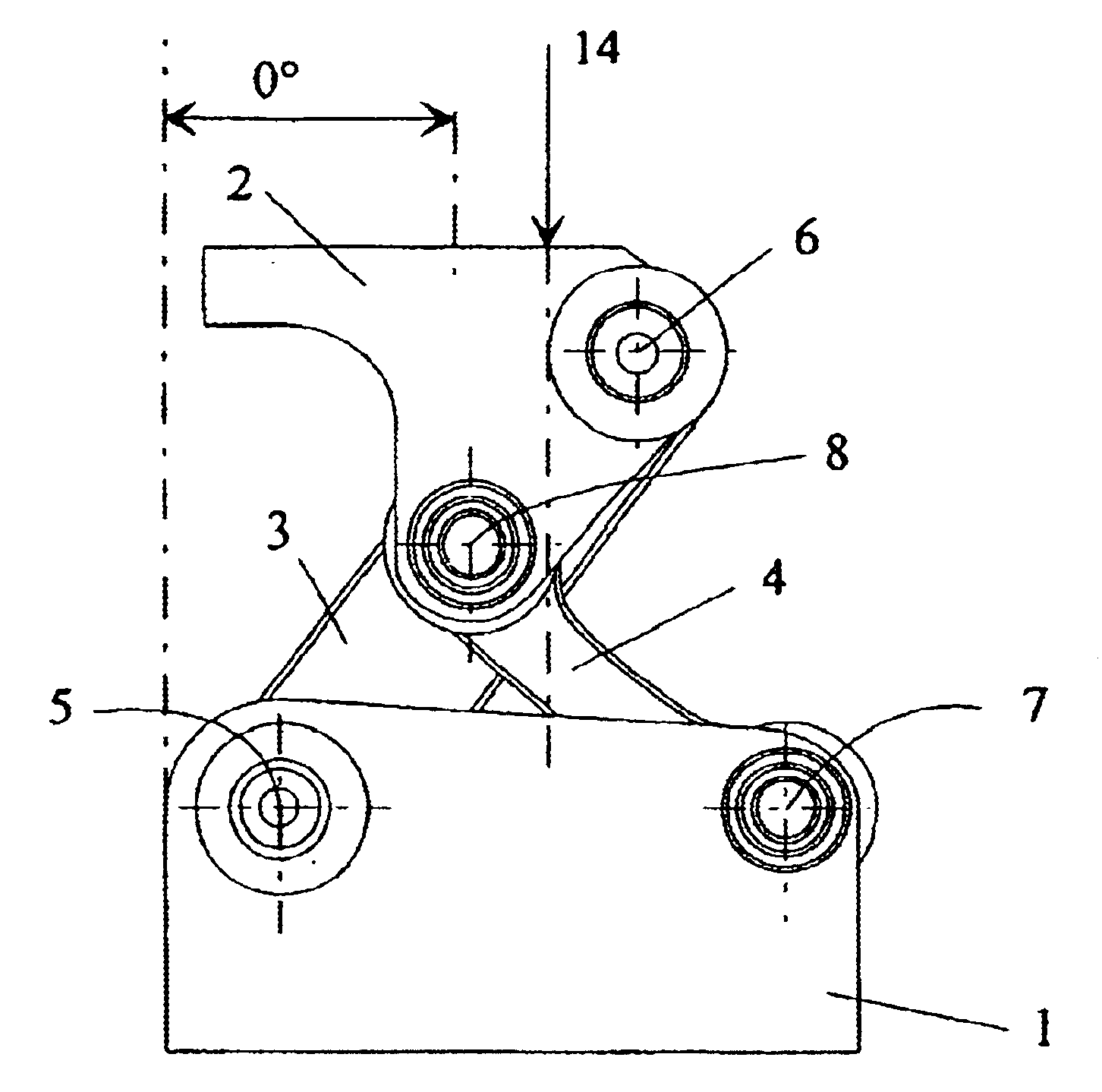
It will be expressly noted here that the following description of the functional model is reversible in its patterns of movement. In this respect, an allocation of reference labels is largely interchangeable.

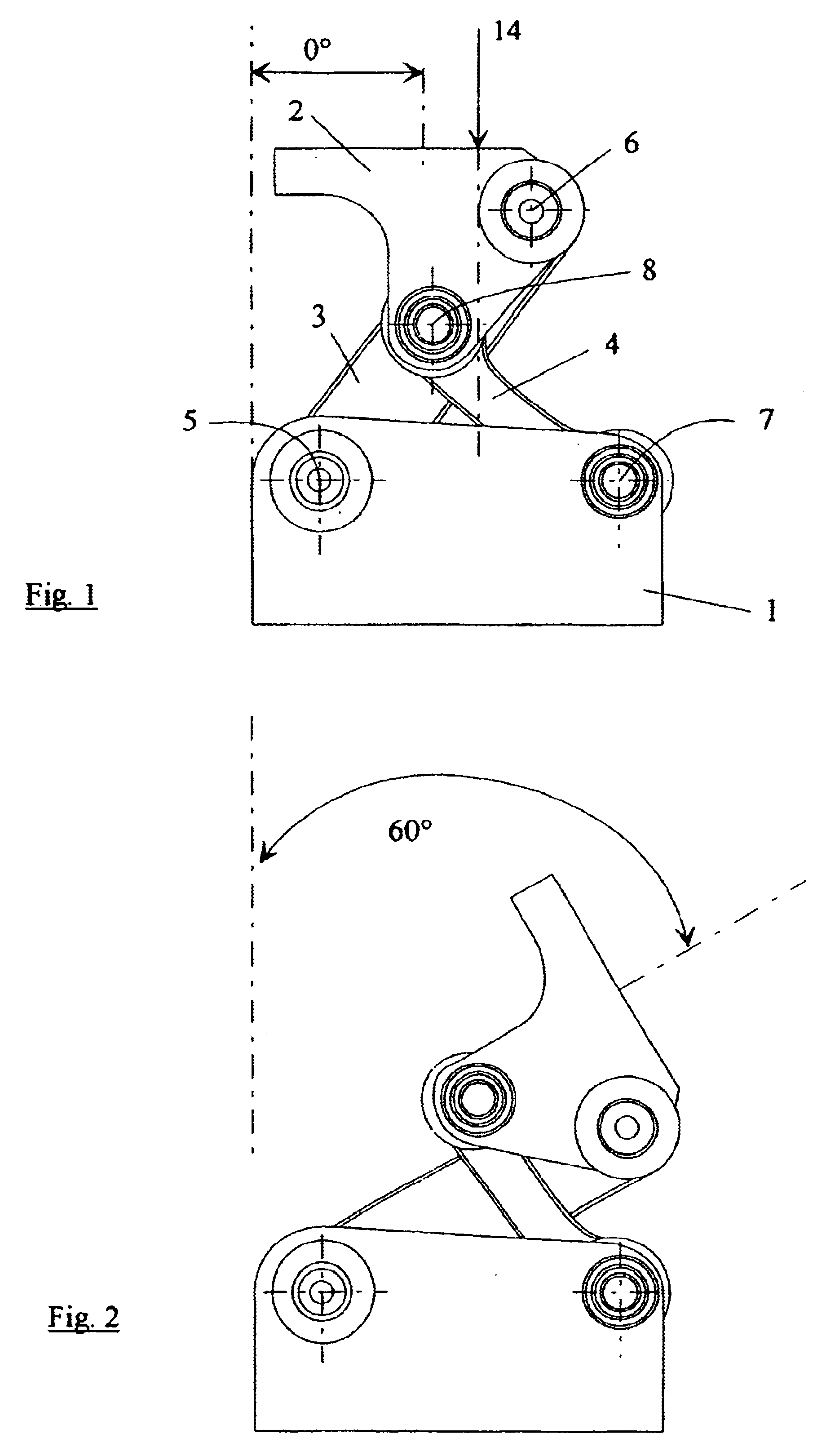
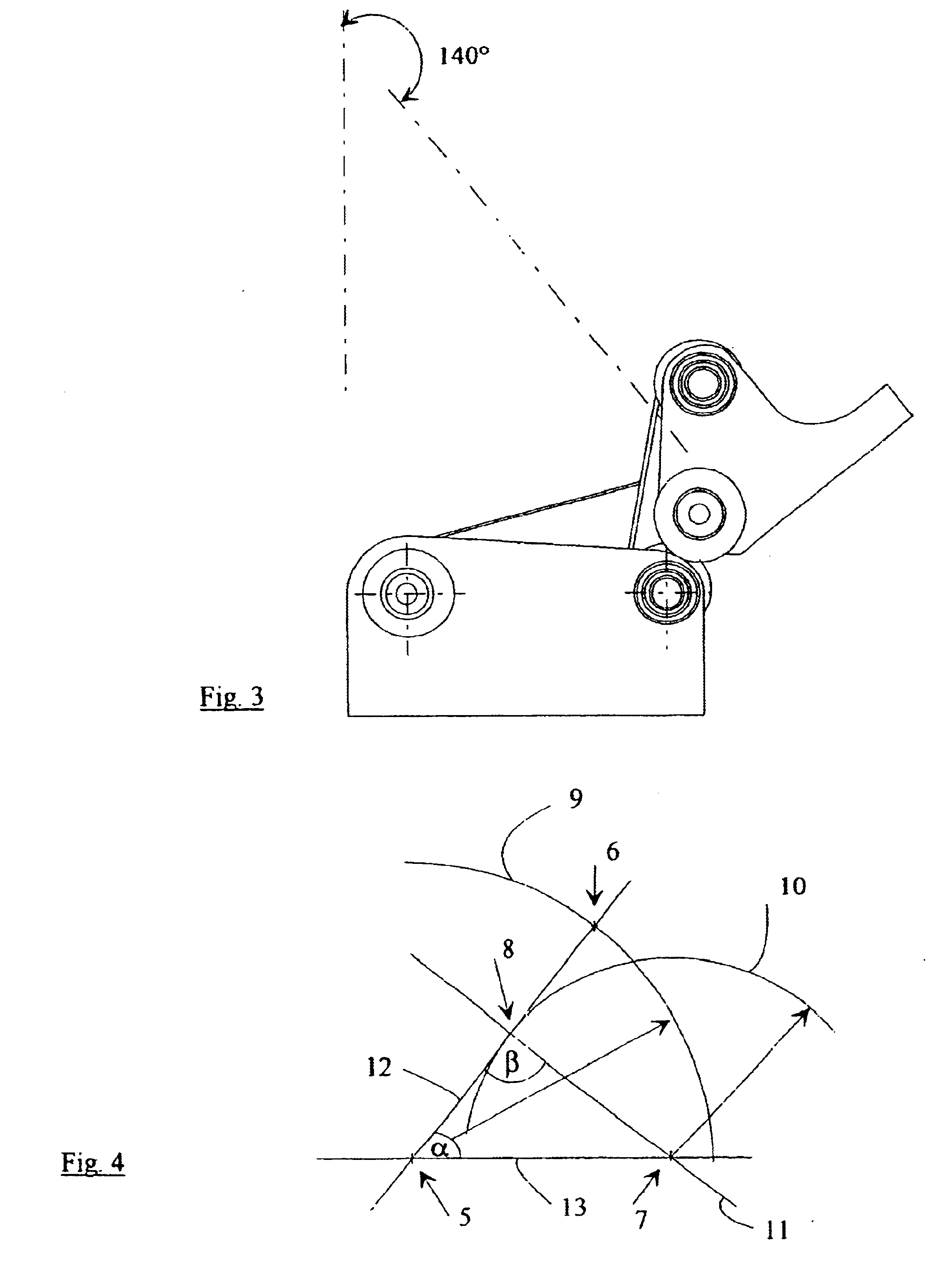
FIGS. 1 through 3 show a functional model of a joint according to the invention in three different settings, where the lower platform 1 is held in a fixed position.

Accordingly, drawings 2 and 3 show an upper platform 2 adjusted relative to the platform 1.

The configurations of the platforms 1, 2 of the functional model are not explained in detail here because these can in principle be designed depending individually on the type of attachment of the prosthesis or the connection to the upper leg.

The platforms 1, 2 are connected by at least two levers 3, 4 of different length which are each articulated at their ends on the platforms 1, 2. The axes 5, 6 of the lever 3 and the axes 7, 8 of the second lever 4 are perpendicular to the plane of the drawing. This allows the joint a relati...


PUM


Abstract

A lower platform and an upper platform are connected first and second levers having different lengths, each lever being articulated about a first axis on said lower platform and a second axis on said upper platform. The upper platform can be swiveled from a rest position to a position of maximum excursion relative to the lower platform so that the distance between platforms is immediately reduced upon swiveling from the rest position. At least one axis is provided with a brake which slows down rotational movement.

Description

The invention relates to a multiaxis joint, especially an artificial knee joint, whose axes of rotation are perpendicular to one plane.DESCRIPTION OF THE RELATED ARTIn prosthetics, artificial knee joints are known which swivel about a single axis, their respective swiveling movement being unsatisfactory, and which in particular permit only an unnatural gait pattern. Multiaxis knee joints have therefore been disclosed whose axes are perpendicular to one plane, for example in accordance with U.S. Pat. No. 5,314,498.In multiaxis knee joints of this type, a polar curve describes the relative movement of the instantaneous center of rotation during swiveling. In this way, a harmonious gait pattern is obtained, because walking on uneven surfaces and stepping over small obstacles and the like is made easier by a shortening of the knee joint. To do this, the leg has to be consciously lifted and, in the process, the instantaneous center of rotation generally shifts forward before the joint co...

Claims


Application Information

Patent Timeline
IPC IPC(8): A61F2/68A61F2/50A61F2/60A61F2/64F16H21/44F16H21/00A61F2/74A61B17/56
CPCA61F2/644A61F2/68F16H21/44A61F2002/5003A61F2002/503A61F2002/5073A61F2002/74A61F2/74
Inventor LUHRS, BERNDTHEILE, FRANKGRIESSER, MICHAELRICHARD, HANS ALBERTKULLMER, GUNTER
Owner WILLOWWOOD GLOBAL LLC
Why Eureka
Try Eureka