Joint prosthesis and method for placement

a joint replacement and prosthesis technology, applied in the field of total joint replacement devices, can solve the problems of failure of "surface replacement" devices, failure of patients' recovery, and damage that is sufficiently severe to require a total joint replacement,

Inactive Publication Date: 2004-06-29
TARABISHY IMAD ED
View PDF13 Cites 186 Cited by
  • Summary
  • Abstract
  • Description
  • Claims
  • Application Information

AI Technical Summary

Problems solved by technology

Frequently, the damage is sufficiently severe to require a total joint replacement.
Many surgeons take this route, even when the underlying bone structure of the femoral head and neck is strong, under the theory that implantation of the shaft within the medullary cavity of the femur is required to obtain the necessary support for the prosthetic femoral head, as the femoral implant is under high stresses that can cause failure of "surface replacement" devices.
Such failures frequently occur early in the patient's recovery, before the bonding of the bone to the metal surfaces of the prosthetic implant has occurred.
Such surgery is very stressful to the patient and increases the risk of infection.
If the device fails, any further implantation of prosthetic devices becomes exceedingly difficult, as the supporting bone structure has already been appreciably reduced.
This surgery comes at a high cost as it is complex, requiring extensive surgical support staff and operating room equipment.
Not withstanding the existence of such prior art prosthetic components and methods for attachment to the human body, it remains clear that there is a need for prosthetic components that may be inserted into the human body without a major incision gain direct access to the femur and hip bone.

Method used


Image

  • Joint prosthesis and method for placement
  • Joint prosthesis and method for placement
  • Joint prosthesis and method for placement

Examples


embodiment 310

As discussed previously, when the patient's bone structure is large enough, a second preferred embodiment, prosthetic components 310, should be used, as illustrated in FIGS. 14, 22 and 23. In preferred embodiment 310, it was possible to insert thicker segments 420a-j (not all of which are shown) than those shown in FIG. 4, eliminating the need for inserting a second shell. Therefore the socket implant 312 comprises the segments 420a-j that are joined to one another to form the first shell 316 and a cup 406. The cup 406 is sized and configured to be received into the interior cavity of the first shell 416. The cup 406 is held in the first shell 416 by the snap ring 445. The cup 406 may be constructed from metal or from synthetic resin. Attachment by a snap ring may be done whether the cup 406 is metal or synthetic resin. The socket implant 312, is now completed. The shaft 414 is very similar in size and shape as shaft 114, described above, and the cup 406 will be sized to receive the...

first embodiment

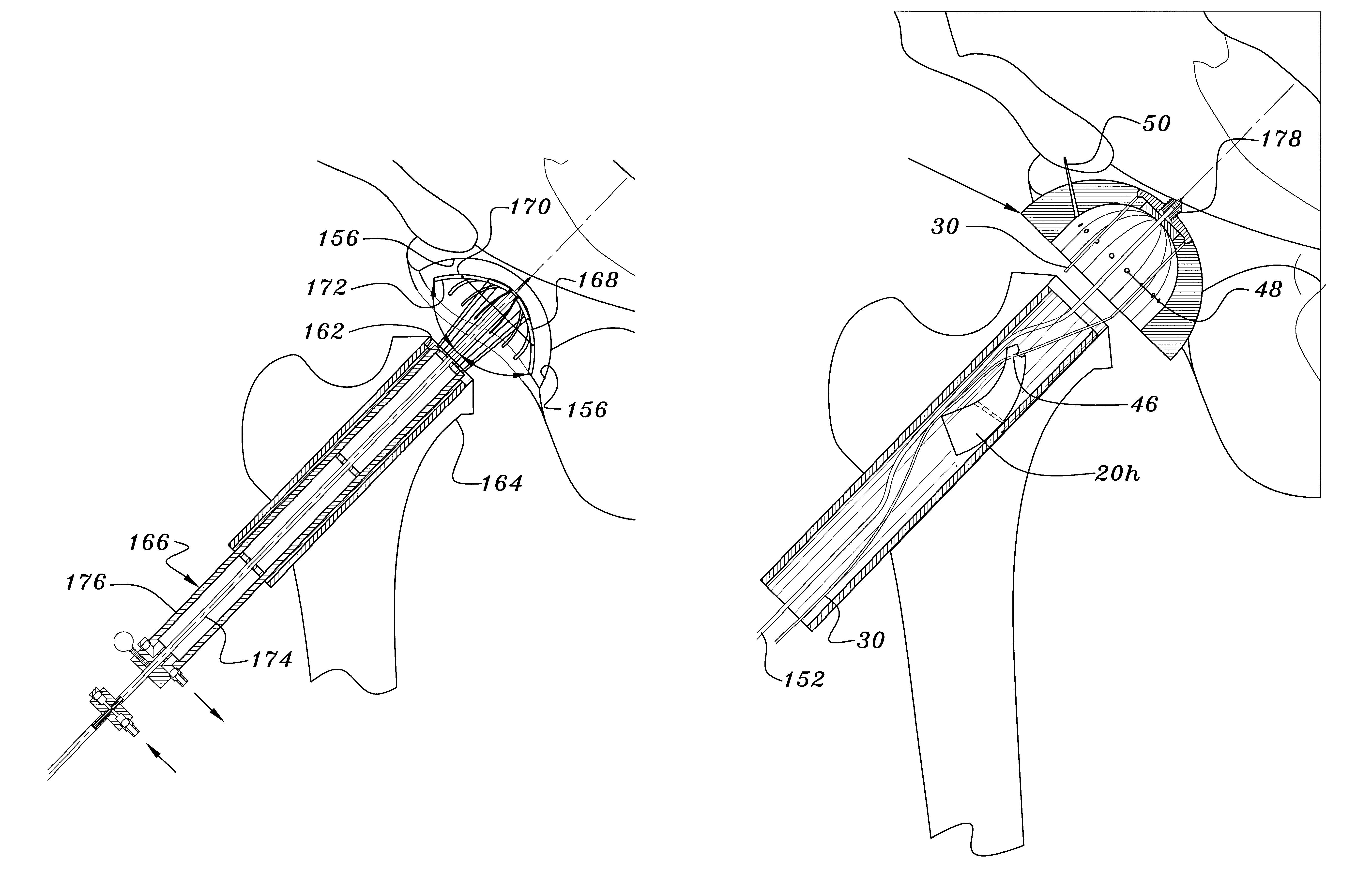
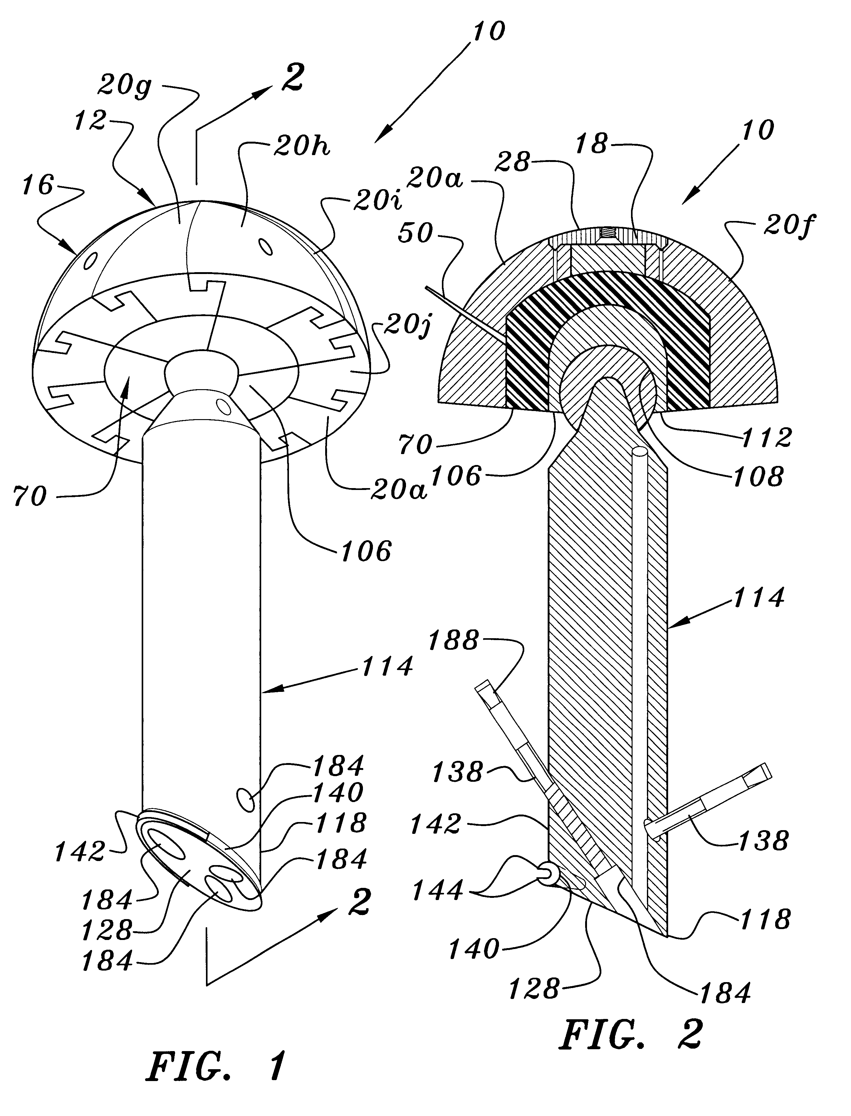
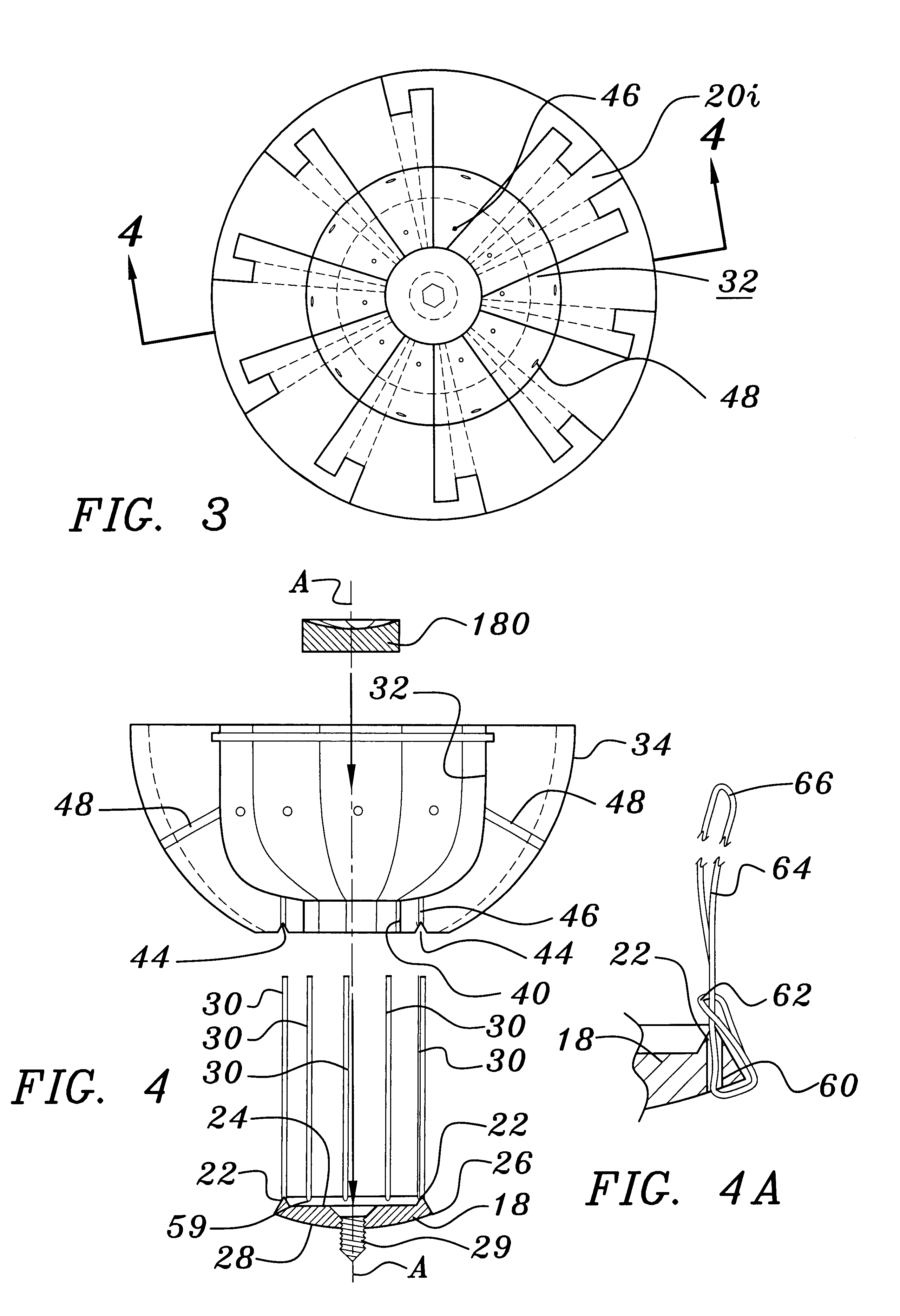
With the site prepared, and the surgeon having selected the prosthetic components 10, the next step is to implant the segmented first shell 16. The base 18 having the cannulated screw 178 inserted therein, is mounted on the guide wire 152 so that the cannulated screw and base 18 passes along the guide wire 152 and is therefore centered in the acetabulum. With the base 18 centered by the guide wire the self-tapping cannulated screw 29 is driven into the bone of the acetabulum of the patient by a cannulated screw driver. The ends of the plurality of flexible wires 30 attached to the base 18 extend outwardly through and beyond the sleeve 160. The first segment to be implanted must be the segment having the two male arms 52, which in FIG. 5 is segment 20h. A flexible secondary guide wire 30 is received through the hole 46 in the first segment 20h so that the segment 28 is slid downwardly on the guide wire until the groove 44 on the first segment 20h engages the ridge 22 of the base 18, ...


PUM


Abstract

A prosthesis for replacement of a ball and socket joint in the human body. The prosthetic components comprise a plurality of separate parts which may be inserted through a hole in the femur of the patient and assembled and attached to the prepared acetabulum of the hip bone to form a cup-shaped first shell. A cup is also passed through the hole in the femur and attached to the first shell to form the socket portion of the joint. A shaft having a first end with a ball formed thereon is inserted in the hole through the femur so that the ball engages the cup for movement therein.

Description

1. Field of the InventionThe present invention relates to a device for total joint replacement, and more particularly to hip and shoulder joint prostheses that require less invasive surgery during installation than required by the current prostheses and methods for placement.2. Description of the Prior ArtArthroplasty, the restoration of normal joint motion, is frequently done by the insertion of metallic prostheses. Implant technology has improved over the last number of years and provides solutions to problems caused by injury, arthritis and other joint diseases. Frequently, the damage is sufficiently severe to require a total joint replacement. The prior art discloses numerous designs for total hip joint prosthetic devices.Total hip joint replacements require interactive prosthetic femoral and acetabular components to emulate the ball-socket mechanism of a natural hip joint. When the supporting structure is weakened, particularly the femoral head and neck, a prosthetic femoral co...

Claims


Application Information

Patent Timeline
Patent Type & Authority Patents(United States)
IPC IPC(8): A61F2/32A61F2/34A61B17/16A61F2/00A61F2/36A61F2/46
CPCA61B17/1617A61B17/1666A61B17/1668A61B17/1684A61F2/32A61F2/34A61F2/3601A61F2/4609A61F2002/30535A61F2250/0058
Inventor TARABISHY, IMAD ED.
Owner TARABISHY IMAD ED
Why Eureka
Try Eureka