
Capacitance type moisture sensor and method of producing the same

a moisture sensor and capacitive technology, applied in the direction of resistance/reactance/impedence, instruments, mechanical means, etc., can solve the problems of moisture sensor breakage, increase production cost, and easy filling of the space between the electrodes with garbag

Inactive Publication Date: 2004-06-29
MATSUSHITA ELECTRIC WORKS LTD
View PDF10 Cites 50 Cited by
  • Summary
  • Abstract
  • Description
  • Claims
  • Application Information

AI Technical Summary

Benefits of technology

With respect to the moisture sensor of the present invention, since the electric field developed between the electrodes provides the moisture detecting region outside the sensor housing through the electrically-insulating wall, it is not necessary to allow the electrodes to project toward the space where the amounts of water should be detected. In particular, when the moisture sensor is used in a garbage disposing apparatus, it is possible to eliminate the problem that the breakage of the moisture sensor is caused by the collision of the garbage with the electrodes, and accurately detect the amounts of water in the garbage in the real-time manner, while preventing the increase in production cost.

Problems solved by technology

That is, since these electrodes project toward the interior of the garbage vessel, a space between the electrodes is easily filled with the garbage.
This leads to an increase in production cost.
In addition, since the garbage is usually stirred in the garbage vessel to facilitate decomposition of the garbage, there is a problem that a breakage of the moisture sensor is accidentally caused by a collision of the garbage with the electrodes.
This also leads to a further increase in production cost.

Method used


Image

  • Capacitance type moisture sensor and method of producing the same
  • Capacitance type moisture sensor and method of producing the same
  • Capacitance type moisture sensor and method of producing the same

Examples


Embodiment Construction

A capacitance type moisture sensor of the present invention is explained in detail according to preferred embodiments.

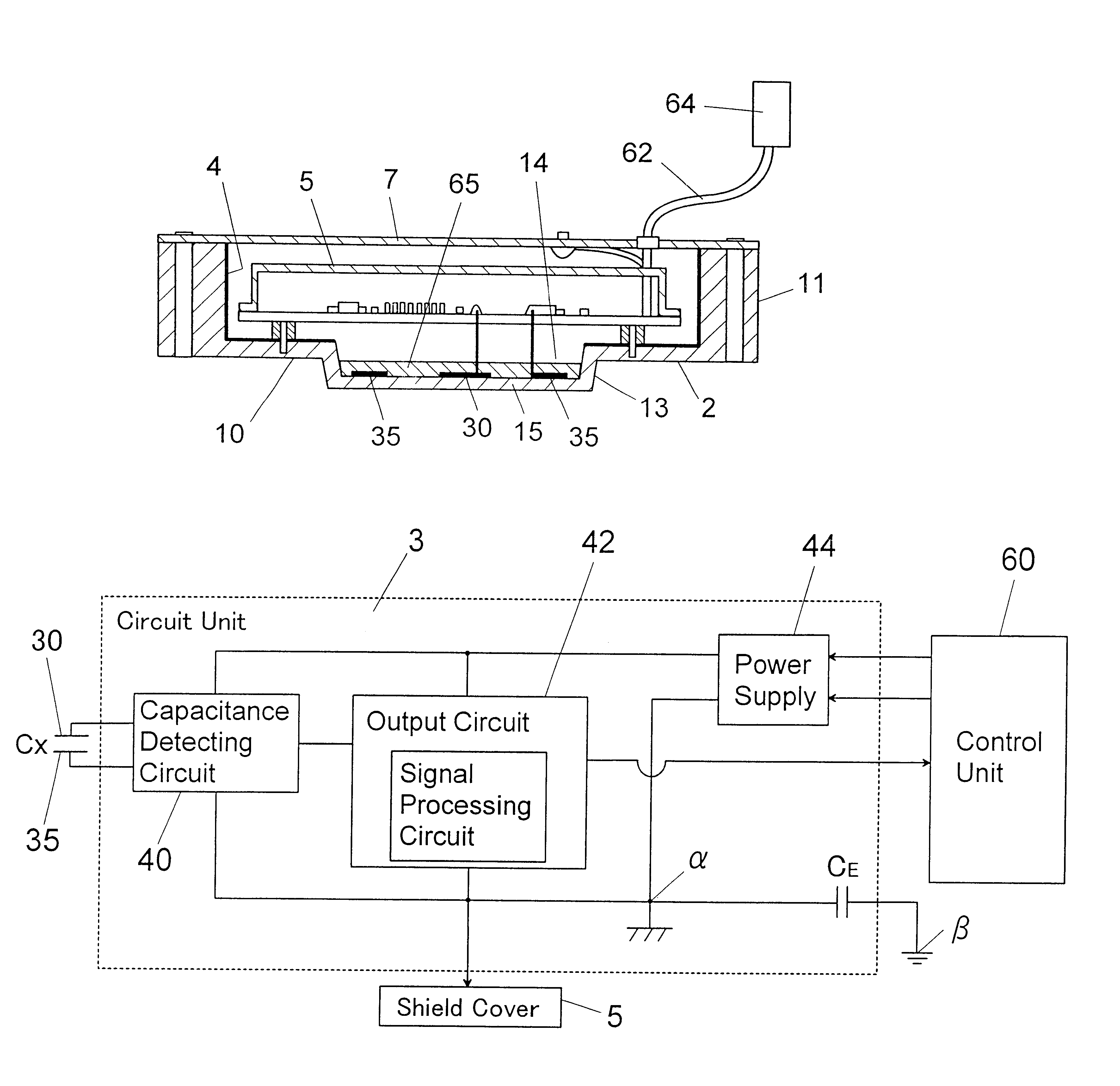
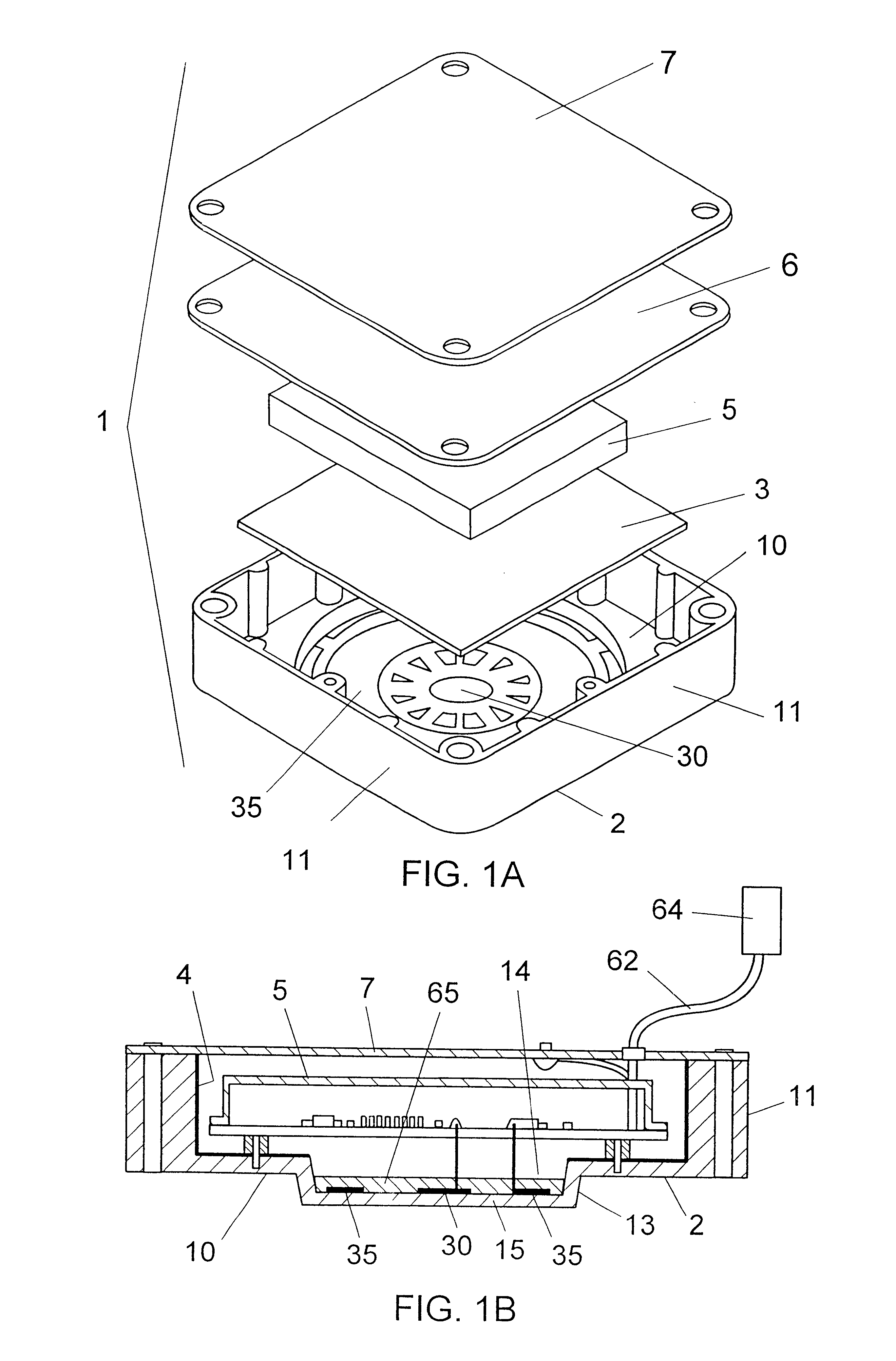
As shown in FIGS. 1A and 1B, the moisture sensor 1 comprises a sensor housing 2, a pair of electrodes 30, 35 disposed in the sensor housing, a printed circuit board 3 mounting electronic parts (not shown) of a circuit unit described later, a shield cover 5, a packing 6, and a conductive cover 7 made of an electrically conductive material, which is attached to a top opening of the sensor housing through the packing 6.

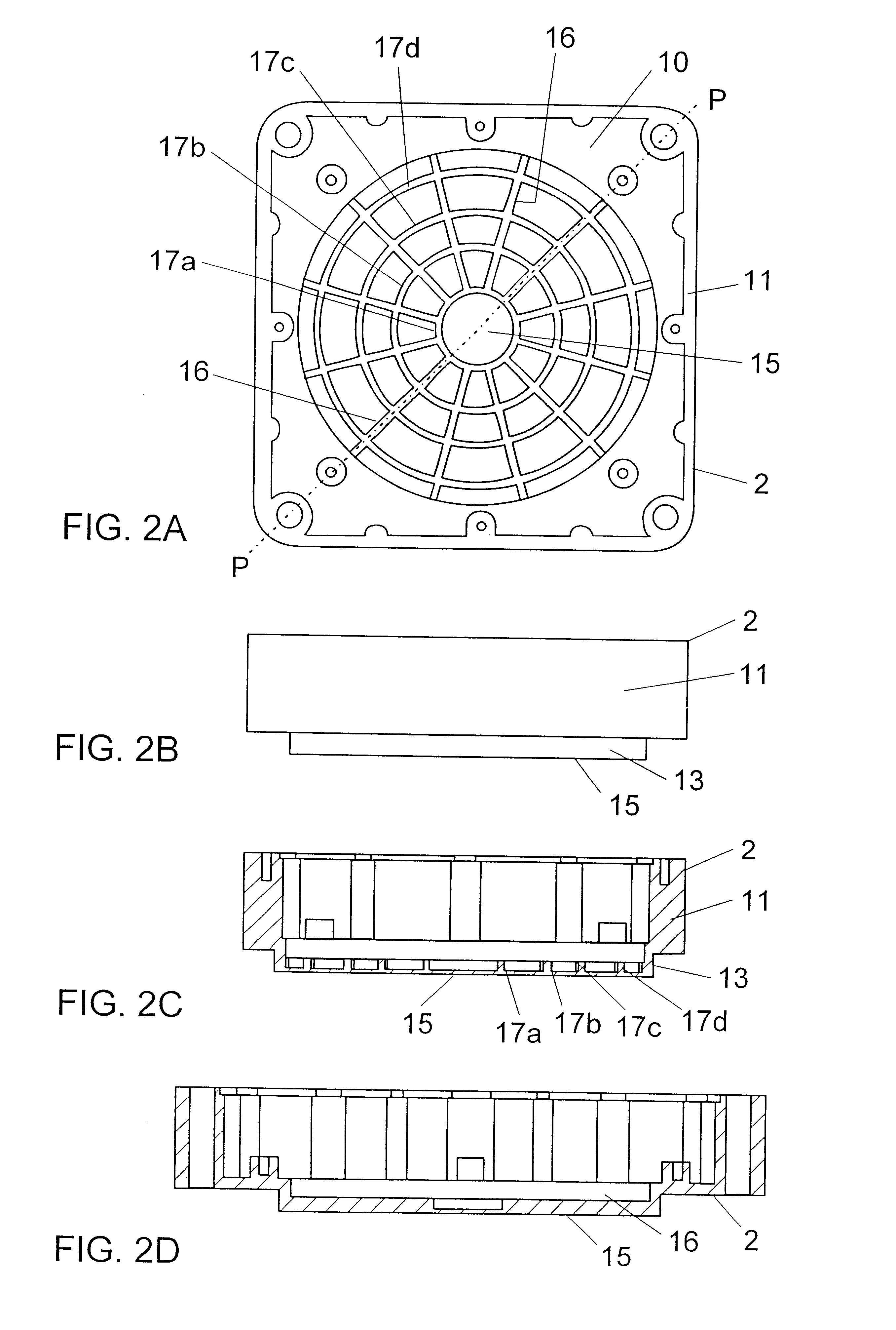
As shown in FIGS. 2A to 2D, the sensor housing 2 has a bottom wall 10 of a substantially square shape, side walls 11 projecting vertically from the circumference of the bottom wall, and a top opening. A circular concave 14 is formed in an inner surface of the bottom wall 10. A bottom of the circular concave is an electrically-insulating wall 15. In addition, a circular convex 13 is formed on an outer surface of the bottom wall 10 at a position opposed to ...


PUM

PropertyMeasurementUnit
relative dielectric constantaaaaaaaaaa
thicknessaaaaaaaaaa

Abstract

A capacitance type moisture sensor having the capability of accurately detecting amounts of water is provided. This sensor has a sensor housing having an electrically-insulating wall, a pair of electrodes disposed on the sensor housing, and a circuit unit. An outer surface of the electrically-insulating wall faces a space where the amounts of water should be detected. On an inner surface of the electrically-insulating wall, at least one of the electrodes is formed. An electric field developed between the electrodes is defined as a moisture detecting region. The circuit unit includes a capacitance detecting circuit for detecting a capacitance value between the electrodes, which changes in response to the amounts of water in the moisture detecting region, and an output circuit for providing an electrical signal corresponding toe the amounts of water according the capacitance value detected by the capacitance detecting circuit.

Description

1. Field of the InventionThe present invention relates to a capacitance type moisture sensor having the capability of accurately detecting amounts of water, and a method of producing the same sensor.2. Disclosure of the Prior ArtCapacitance type moisture sensor is known as a kind of conventional moisture sensor, and detects amounts of water from a change of capacitance between a pair of electrodes in accordance with the nature that water is a polarization (dielectric) material.For example, this type of moisture sensor is built in a garbage disposing apparatus, and used to detect amounts of water in the garbage. That is, as shown in FIGS. 21A and 21B, the moisture sensor comprises an electrically-insulating panel 2P, which is attached to an opening formed in a garbage vessel 100P of the garbage disposing apparatus, a pair of electrodes 30P, 35P arranged in parallel on the electrically-insulating panel, a capacitance detecting circuit 40P for detecting a capacitance value (Cx) between...

Claims


Application Information

Patent Timeline
Patent Type & Authority Patents(United States)
IPC IPC(8): G01R27/26G01N27/22
CPCG01R27/2605G01N27/22
Inventor HIRONO, ATSUYUKIMORI, HIDEOTAKADA, YUJIYOSHIKAWA, KEISUKE
Owner MATSUSHITA ELECTRIC WORKS LTD
Learn More