Eureka AIR delivers breakthrough ideas for toughest innovation challenges, trusted by R&D personnel around the world.

Key switch

a key switch and switch body technology, applied in the field of key switches, can solve the problems of low flexibility in disposing the push button on the print wiring board, cumbersome assembly tasks, and low productivity, and achieve the effects of low parts count, easy assembly tasks, and outstanding productivity

Inactive Publication Date: 2004-07-06
NEC CORP
View PDF7 Cites 18 Cited by
  • Summary
  • Abstract
  • Description
  • Claims
  • Application Information

AI Technical Summary

Benefits of technology

In view of the foregoing problems and disadvantages of the conventional technology, it is therefore an object of the present invention to provide a key switch capable of providing outstanding productivity because of easy assembly tasks and a low parts count, high degree of flexibility in disposing the key switch on a print wiring board, and advantages in visual recognition from other directions than an upper part of the key top.
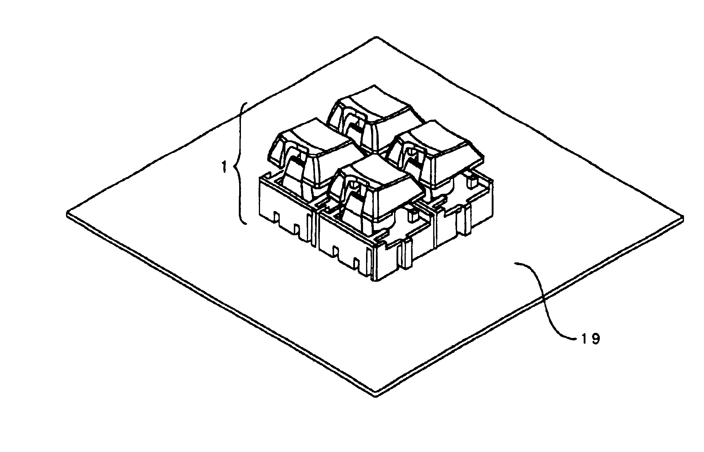
Adjacent key switches may be engagable to each other by fitting a convex portion protruded from the above-mentioned switch base on one side to a concave portion formed in the above-mentioned switch base on the other side of the above-mentioned key switch. Thus, the key switches adjacent to each other can be combined firmly with a simple composition.

Problems solved by technology

However, the above-mentioned illuminated push button described in unexamined Japanese Patent Publication No.
The connector is required to be installed and soldered on the reverse side of an installed LED, thus causing the problems of cumbersome assembly tasks and lower productivity.
In the event of changing positions of a push button, boards for fixing the push button must be prepared for each disposition of the push button, which causes a problem of having low flexibility in disposing the push button on the print wiring board.
Further, a problem also arises in that a high parts count results in high manufacturing costs, because eight parts are required besides the LED to be installed on the print wiring board.
Hei 4-127929 also causes the problems of cumbersome assembly tasks and lower productivity, because the LED must be soldered after installing an LED holder on a substrate disposed on a membrane adjacent surface for each switch unit, and the housing composed to cover the LED is fixed by brackets.
While the key top is not depressed, a light emitting surface of the LED is in a state of being buried in the key top, which causes a problem of providing a poor visual recognition for other directions than the upper part of the key top.
Furthermore, a problem arises in that a high parts count results in high manufacturing costs, because six parts are required besides the LED to be installed on the print wiring board.

Method used


Image

  • Key switch
  • Key switch
  • Key switch

Examples


second embodiment

Referring now to FIG. 10, the key switch relating to the present invention is described.

first embodiment

The key switch 41 relating to the present embodiment is indicated in the event of extending a side in the shape of the button base 4 to be twice in length and can be corresponded only by changing the button base 4 of the key switch 1 in the first embodiment to a button base 44. Thus, key switches having button bases in various shapes can be disposed functionally on an operation panel, which can achieve enhancement of operability and development to designing of operation panel surfaces effectively.

third embodiment

Referring now to FIG. 11, the key switch relating to the present invention is described.

The key switch 51 relating to the present embodiment is indicated in the event of expanding the shape of the button base 4 to be four times in size and can be corresponded only by changing the button base 4 of the key switch 1 in the first embodiment to a button base 54. Thus, similar effects as the second embodiment can be obtained.

As clear from the description above, according to the present invention, a key switch with high productivity, high degree of flexibility in disposing on a print wiring board and excellent visual recognition from other directions than an upper part of the key top can be provided.


PUM


Abstract

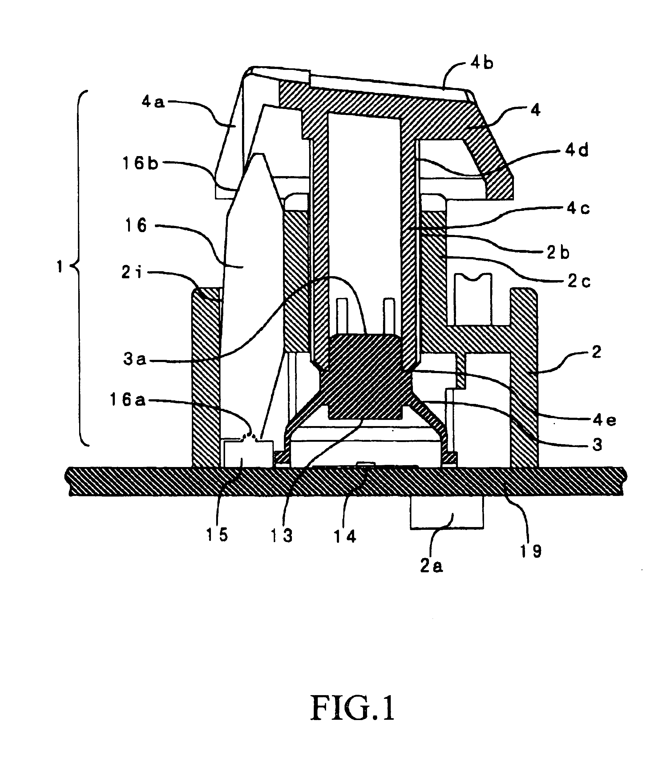
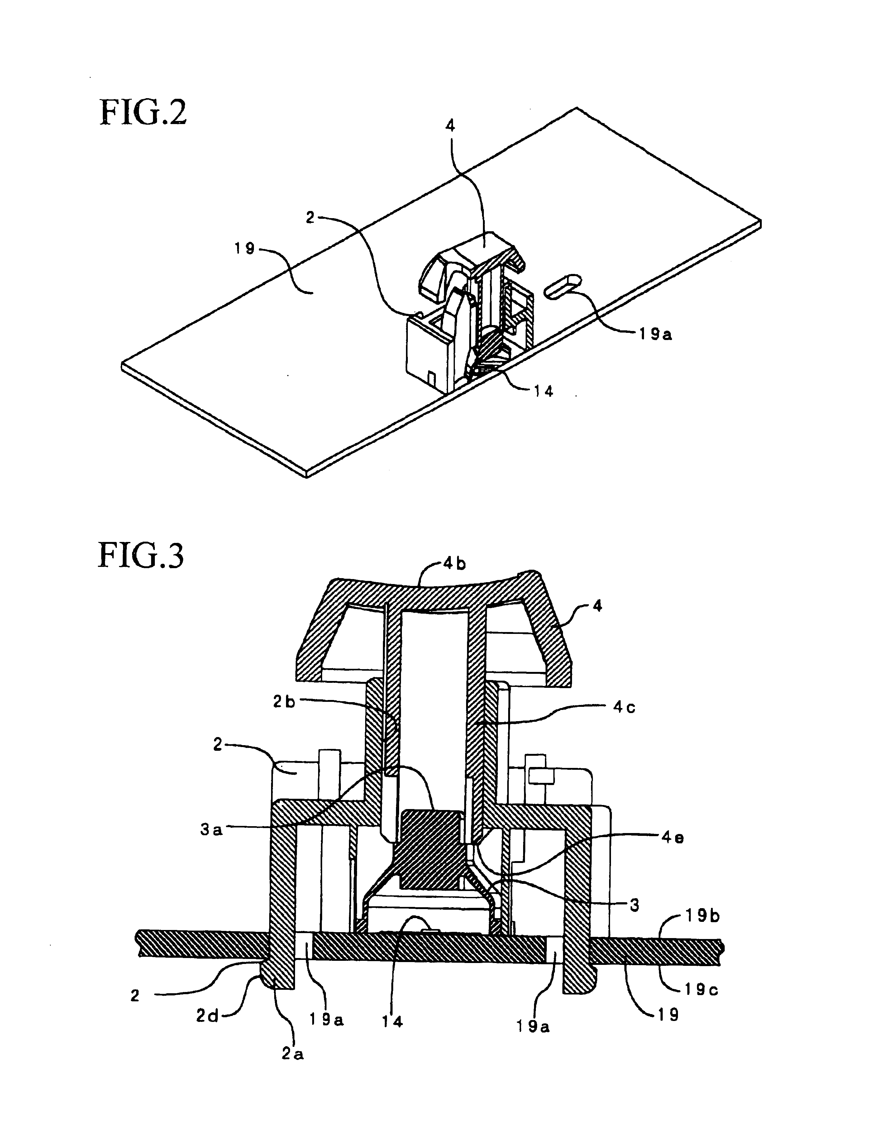
A base button 4 wuth a button depressing surface and a shaft portion, and a shaft supporting portion for slidably supporting the shaft portion of the button base 4 are provided. A switch base installable on a print wiring board, a contact rubber providing a conductive portion at a position facing the print wiring board , and a light emitting portion provided on the print wiring board are also included. The shaft portion is lowered by depressing the button depressing surface of the button base 4 and the conductive portion of the contact rubber is lowered until the conductive portion contacts an electrical contact on the print wiring board. Thus, an electrical contact function is exerted and the light emitting portion emits light, when the conducts portion comes into contact with the electrical contact.

Description

BACKGROUND OF THE INVENTIONThe present invention relates to a key switch and more particularly to a push-button key switch used in communications units, keyboards for data inputting, operating panels, and the likesConventionally, a key switch whose light emitting portion of an integrated LED or the like illuminates on pressure of a push button Switch is variously used in communications units, keyboards for data inputting, operating panels, aid the like.For example, an illuminated push button described in unexamined Japanese Patent Publication No. Hei 11-73838 has an LED and provides a print board on which a wiring pattern is integrated into a base, thus providing for an illuminated push button capable of leading light emitted from a luminous element to a display portion without passing the light through a member manufactured with a sealant Disposed sequentially in a vertical direction on the print board are a silicon cover functioning as a sealant in which a reflect case is integrat...

Claims


Application Information

Patent Timeline
Patent Type & Authority Patents(United States)
IPC IPC(8): H01H13/70H01H11/00H01H13/02
CPCH01H13/70H01H11/0018H01H2207/00H01H2219/036H01H2219/062H01H2219/066H01H2221/07H01H2233/034
Inventor KURIHARA, AKIO
Owner NEC CORP
Why Eureka
Eureka Blog
Learn More