Masked coating blade

a coating blade and masking technology, applied in the field of coating blades, can solve the problems of affecting the quality of coated paper in an unacceptable manner, affecting the productivity of coating paper, and needing replacement,

Active Publication Date: 2022-10-11
BTG ECLEPENS
View PDF32 Cites 0 Cited by
  • Summary
  • Abstract
  • Description
  • Claims
  • Application Information

AI Technical Summary

Benefits of technology

[0010]It is an object of the present invention to provide a coating blade for the application of coating color to a fibrous web, allowing for excellent coating quality and outstanding operational productivity. It is thus an object of the present invention to provide a coating blade having an operating zone intended for contact with a coating color, the operating zone being indisposed for affecting negatively the fluid dynamics in the coating color. It is another object of the present invention to provide a coating blade having an operating zone intended for contact with a coating color, the operating zone being indisposed of affecting negatively the flexibility of the coating blade. It is a further object of the present invention to provide such a coating blade having improved surface properties.

Problems solved by technology

Pigment particles in the coating color fluid subject the coating blade to both abrasive and erosive wear.
Worn out coating blades affect the quality of the coated paper in an unacceptable manner and need to be replaced.
In case of a blade change the coating machine is either stopped for up to one hour, causing a productivity loss, or still operated during 5-10 minutes, in which period the paper produced needs to be scrapped.
Replacement of coating blades are furthermore costly due to the need to “run in” a new coating blade for up to 30 minutes before it can be used to produce coated paper of acceptable quality.
Wear-resistant deposits are intrinsically hard and / or rigid, thus affecting the flexibility of the coating blade.
This strongly rigidifies the structure, resulting in limited blade flexibility (in the machine direction and in the cross / transversal direction).
It has been found that an abrupt or steep transition at the upstream longitudinal boundary of the wear-resistant deposit, opposite to the longitudinal edge of the coating blade, from the surface of the wear-resistant deposit to the surface of the steel substrate negatively affects the surface quality of the paper coating.
Such residues, or “stickies”, cause streaks in the paper coating and thus lead to quality issues.

Method used


Image

  • Masked coating blade
  • Masked coating blade

Examples


example

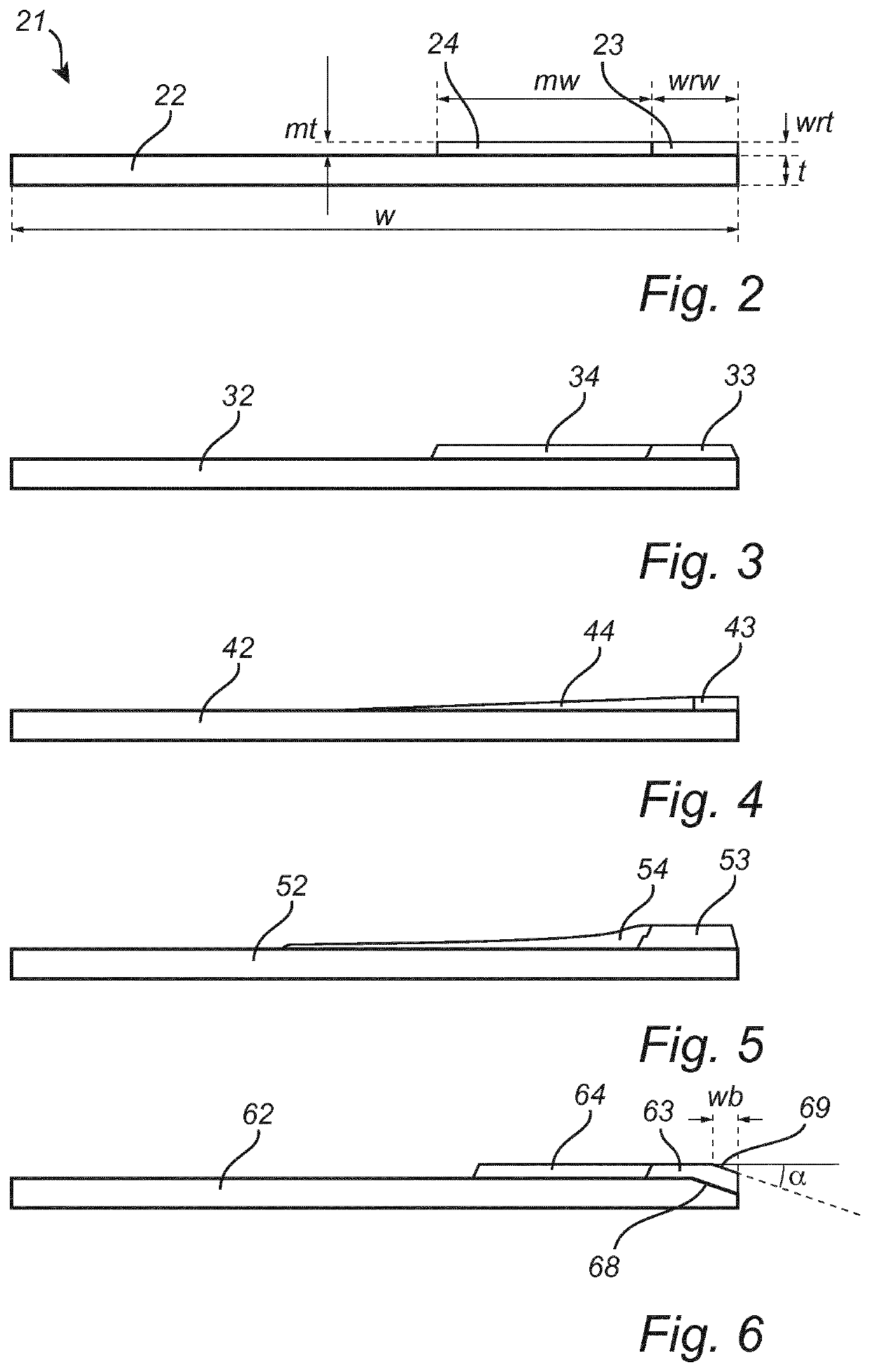
[0043]A reference coating blade was manufactured by providing a stainless steel substrate of 100 mm width and 0.457 mm thickness with a Cr2O3 based wear-resistant deposit of 5 mm width. A test coating blade according to the invention was manufactured by providing a stainless steel substrate of 100 mm width and 0.457 mm thickness with a Cr2O3 based wear-resistant deposit of 5 mm width and an adjoining polyurethane masking deposit of 15 mm width. The masking material was applied as a solvent based dispersion of methyl diphenyl diisocyanate (MDI) based polyurethane. The wear-resistant deposits had a sliding bevel of 10°.

[0044]The test and reference coating blades, respectively, were used to top-coat a paper web in a Jagenberg Combiblade coater at the following machine conditions and settings.

Coating Station Configuration:

[0045]Pre-coat (both paper sides—film press; 5-7 g / m2)

[0046]Middle-coat (top paper side—coating rod; 7-8 g / m2)

[0047]Top-coat (top paper side—bent blade; 9-10 g / m2)

Mach...


PUM

PropertyMeasurementUnit
widthaaaaaaaaaa
thicknessaaaaaaaaaa
widthaaaaaaaaaa

Abstract

In a general aspect, a coating blade for application of coating color to a fibrous web can include an elongate substrate having a longitudinal edge. Within an operating zone of the coating blade intended for contact with a coating color, the elongate substrate can include a longitudinal wear-resistant deposit adjacent to the longitudinal edge. The coating blade, within the operating zone, can also include a longitudinal masking deposit adjoining the longitudinal wear-resistant deposit.

Description

CROSS REFERENCE TO RELATED APPLICATIONS[0001]This application is a national stage entry of PCT Application No. PCT / EP2017 / 057581, filed on Mar. 30, 2017, entitled “MASKED COATING BLADE”, which claims the benefit of European Application No. 16163276.5, filed on Mar. 31, 2016, entitled “MASKED COATING BLADE”, the disclosures of which are both hereby incorporated by reference in their entireties.TECHNICAL FIELD[0002]The present invention relates to a coating blade for application of coating color to a fibrous web.BACKGROUND ART[0003]In the art of coating paper, coating color is applied using a coating blade. Coating blades are known in the art also as doctor blades or scrapers, all of which will be referred to herein as coating blades. The coating blade is typically constituted by a steel substrate onto which a deposit has been applied. For the purpose of coating the paper, an excess of coating color liquid is applied to the surface of the paper and subsequently doctored off using the ...

Claims


Application Information

Patent Timeline
Patent Type & Authority Patents(United States)
IPC IPC(8): D21H23/34B05C11/04D21H25/10D21G3/00
CPCD21H23/34B05C11/045D21G3/005D21H25/10
Inventor CLAUDON, ALEXANDRE
Owner BTG ECLEPENS
Why Eureka
Try Eureka