Liquid crystal display device

a liquid crystal display and display device technology, applied in the field of liquid crystal display devices, can solve the problems of difficult to realize a high contrast ratio, transmittance loss, light amount, etc., and achieve the effect of high contrast ratio, excelling productivity, and cost reduction

Active Publication Date: 2016-03-01
SHARP KK
View PDF25 Cites 0 Cited by
  • Summary
  • Abstract
  • Description
  • Claims
  • Application Information

AI Technical Summary

Benefits of technology

[0168]According to the present invention, there can be provided a liquid crystal display device which enables costs to be reduced, excels in productivity, and enables a high contrast ratio over a wide viewing angle range to be realized. This liquid crystal display device can preferably be employed for a display device such as an outdoor signage display or the like.

Problems solved by technology

With such a TN mode liquid crystal display device, inexpensive manufacturing technology has been established, and industrially matured, but it has been difficult to realize a high contrast ratio.
Even in such an MVA mode wherein the inclination directions of liquid crystal molecules have been divided into four domains, Schlieren texture or alignment to an unintentional direction has frequently been observed at boundaries between domains or in the vicinity of alignment control means, causing transmittance loss.
Unless this unnecessary reflection is prevented, even with a display device which realizes generally complete black display in a dark room environment, light amount at the time of black display of the display device increases when observing in a bright environment, and consequently, the contrast ratio deteriorates.
Also, with the above (C), (D), and (E) methods, there has been room for improvement in that there is needed a biaxial retardation film satisfying a relation of nx>nz>ny (satisfying a relation of 01) which is difficult to be manufactured and high in costs.

Method used


Image

  • Liquid crystal display device
  • Liquid crystal display device
  • Liquid crystal display device

Examples


Embodiment Construction

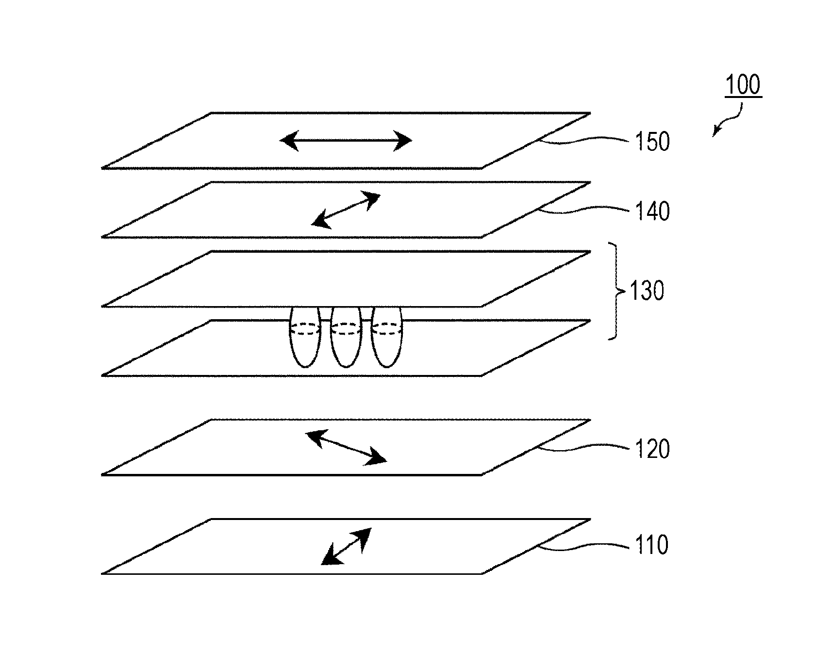
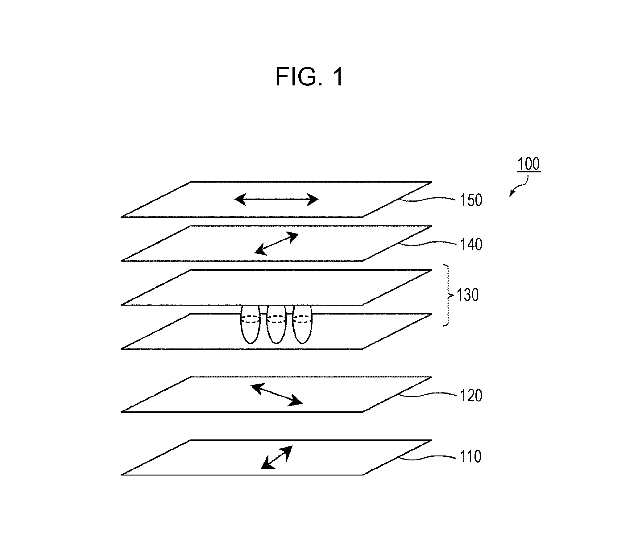
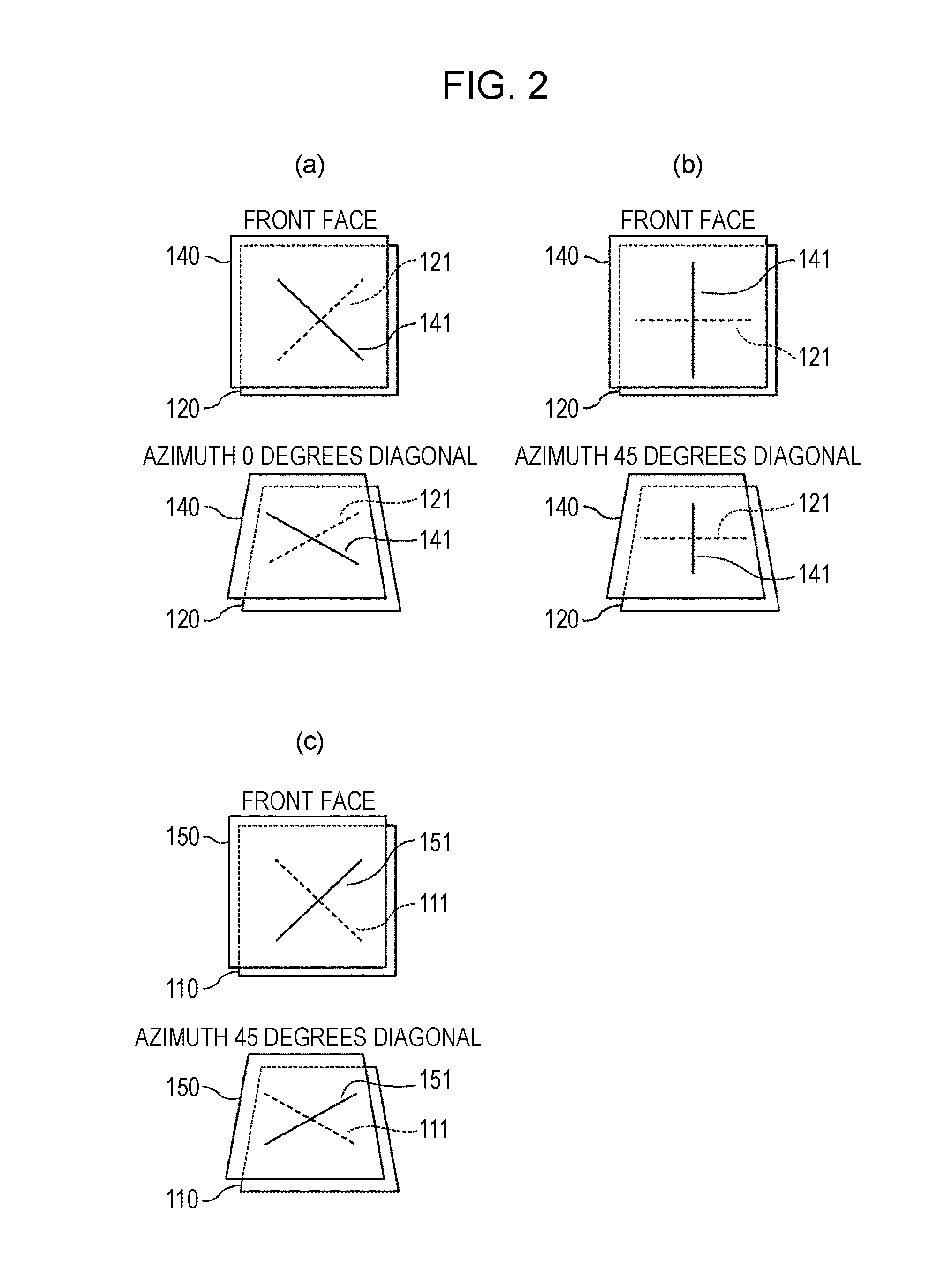
[0193](Birefringent Layers)

[0194]Birefringent layers to be employed for the present invention are not particularly restricted regarding material and optical performance, and there may be employed, for example, a drawn polymer film, a liquid crystal material of which the alignment has been fixed, a thin plate configured of an organic material, and so forth. A method for forming a birefringent layer is not particularly restricted, and according to design conditions, the most productive method may be selected as appropriate. In the case of a birefringent layer formed from a polymer film, a solvent cast method, a melt extruding method or the like may be employed for example. A method for forming multiple birefringent layers at the same time may be employed according to a co-extrusion method. As long as desired retardation is expressed, a birefringent layer may or may not be drawn. A drawing method is not particularly restricted, and there may be employed, for example, a special drawing ...


PUM

PropertyMeasurementUnit
thickness direction retardationaaaaaaaaaa

Abstract

The present invention provides a liquid crystal display device which enables costs to be reduced, excels in productivity, and enables a high contrast ratio over a wide viewing angle range to be realized. The present invention is a liquid crystal display device including a first polarizer, a second-type (nx<ny≦nz) birefringent layer, a first λ / 4 plate (nx>ny≧nz), a liquid crystal cell, a second λ / 4 plate having an Nz coefficient different from the first λ / 4, and a second polarizer in this order, wherein an in-plane slow axis of the first λ / 4 plate forms generally 45 degrees as to an absorption axis of the first polarizer, an in-plane slow axis of the second λ / 4 plate is generally orthogonal to the in-plane slow axis of the first λ / 4 plate, an absorption axis of the second polarizer is orthogonal to the absorption axis of the first polarizer, an in-plane fast axis of the second-type birefringent layer is generally orthogonal to the absorption axis of the first polarizer, and black display is performed by aligning liquid crystal molecules within a liquid crystal layer in a manner generally perpendicular to substrate faces.

Description

[0001]This application is the U.S. national phase of International Application No. PCT / JP2012 / 057431 filed 23 Mar. 2012 which designated the U.S. and claims priority to JP 2011-080126 filed 31 Mar. 2011, the entire contents of each of which are hereby incorporated by reference.TECHNICAL FIELD[0002]The present invention relates to a liquid crystal display device, and more specifically relates to a VA (Vertical Alignment) mode liquid crystal display device employing a circularly-polarizing plate.BACKGROUND ART[0003]Liquid crystal display devices have widely been employed as display devices of various information processing apparatuses including computers and televisions. In particular, TFT type liquid crystal display devices (hereinafter, also referred to as “TFT-LCD”) have come into widespread use, and further market growth is anticipated, leading to demand for further improvement in image quality. Hereinafter, description will be made with a TFT-LCD as an example, but the present in...

Claims


Application Information

Patent Timeline
Patent Type & Authority Patents(United States)
IPC IPC(8): G02F1/1335G02F1/13363G02B5/30G02B27/28G02F1/1337
CPCG02F1/133634G02B5/3083G02B27/286G02F1/13363G02F1/133528G02F1/1393G02F1/133502G02F2001/133541G02F2001/133638G02F2001/133742G02F2202/36G02F2413/03G02F2413/04G02F2413/05G02F2413/02G02F2413/11G02F1/133541G02F1/133638G02F1/133742
Inventor SAKAI, AKIRA
Owner SHARP KK
Why Eureka
Try Eureka