Imaging apparatus

a technology of imaging apparatus and recursive nr operation, which is applied in the direction of instruments, television systems, color signal processing circuits, etc., can solve the problems of deteriorating vertical resolution and uncomfortable feeling in recursive nr operation, and achieve the effect of preventing uncomfortable feeling

Inactive Publication Date: 2004-07-06
PANASONIC CORP
View PDF9 Cites 6 Cited by
  • Summary
  • Abstract
  • Description
  • Claims
  • Application Information

AI Technical Summary

Benefits of technology

to provide an imaging apparatus that has functions to use the both-fields signals of the interlaced signal for the recursive noise reduction in the normal ope...

Problems solved by technology

As a result, the vertical resolution is deteriorated.
In addition, when the normal operation is changed to the accumulation sensitivity increase opera...

Method used


Image

  • Imaging apparatus
  • Imaging apparatus
  • Imaging apparatus

Examples


first embodiment

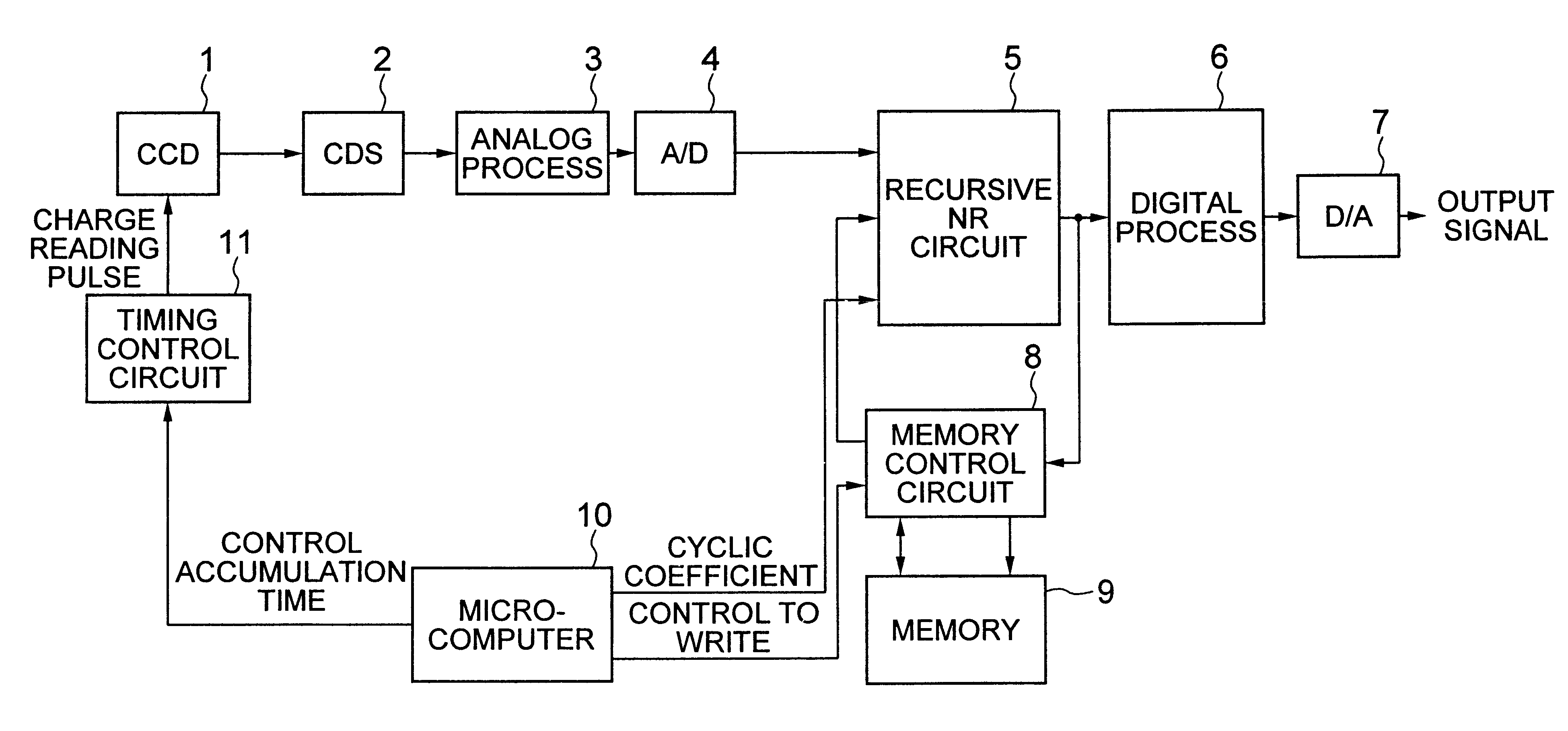
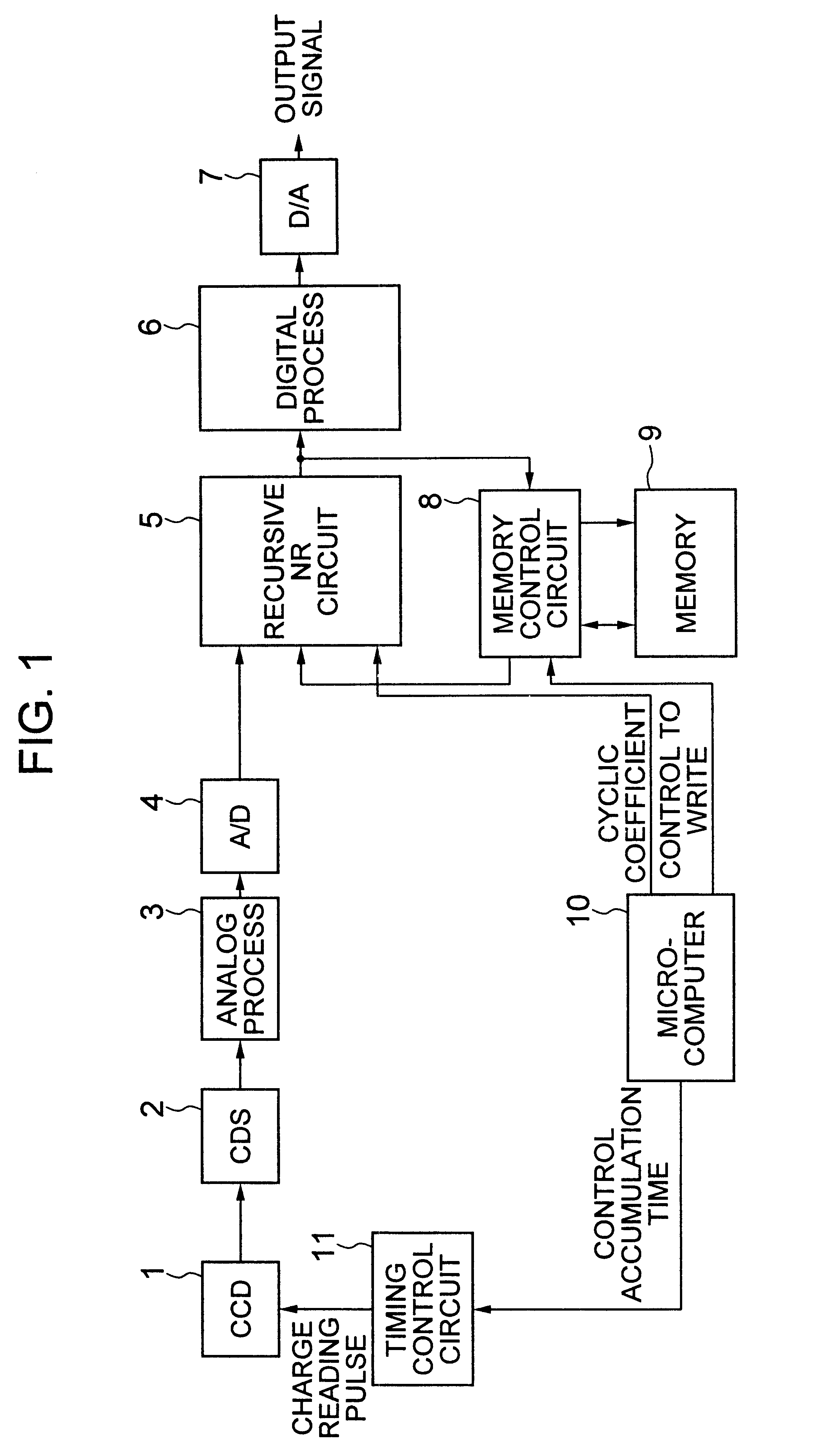
FIG. 1 is a block diagram showing the schematic construction of the imaging apparatus according to the first embodiment of the invention.

The imaging apparatus shown in FIG. 1 includes: a CCD 1 (the imaging means) for converting a light image into an electrical image signal; a CDS 2 for sampling the electrical image signal; an analog process circuit 3 for performing an analog signal process to the sampled image signal; an A / D (analog / digital conversion) circuit 4 for converting the analog-signal processed image signal into a digital signal; a recursive NR circuit 5 (the recursive noise reduction means) for performing a recursive filtering process to the digital image signal in the time-axis direction to reduce the noise component of this image signal; a digital process circuit 6 for performing a necessary signal process to the recursive-filtering processed image signal, a D / A (digital / analog conversion) circuit 7 for converting the necessary-signal processed image signal into an anal...

second embodiment

The imaging apparatus according to the second embodiment of the invention will be described. FIG. 14 is a block diagram showing the schematic structure of the imaging apparatus. In the imaging apparatus shown in FIG. 14, the same blocks as those of the imaging apparatus shown in FIG. 1 are identified by the same reference numerals, and their constructions and operations will not be described.

The imaging apparatus shown in FIG. 14 is different from the imaging apparatus shown in FIG. 1 in that the output signal of the recursive NR circuit 5 is supplied not to the digital process circuit 6, but to the memory control circuit 8, and the output signal of the memory control circuit 8 is supplied to the digital process circuit 6.

The operation of this imaging apparatus will be described below.

In this imaging apparatus, the recursive NR circuit 5 performs the recursive filtering process to the image signal in the time-axis direction, and the memory control circuit 8 controls the memory 9 to ...

third embodiment

The imaging apparatus according to the third embodiment of the invention will be described below. FIG. 26 is a schematic block diagram of the imaging apparatus according to the third embodiment. In the imaging apparatus shown in FIG. 26, the same blocks as those of the imaging apparatus shown in FIG. 1 are identified by the same reference numerals, and their constructions and operations will not be described.

The imaging apparatus shown in FIG. 26 is different from the imaging apparatus shown in FIG. 1 in that the output signal of the recursive NR circuit 5 is supplied not to the digital process circuit 6, but to the memory control circuit 8, and the output signal of the memory control circuit 8 is supplied as the first output signal to the recursive NR circuit 5 and as the second output signal to the digital process circuit 6.

The operation of this imaging apparatus will be described.

In this imaging apparatus, the recursive NR circuit 5 performs the recursive filtering process to ima...


PUM


Abstract

An imaging apparatus includes a CCD for accumulating an image signal by an n-times long-time-accumulation (n is an integer of "1" or more); a timing control circuit for controlling to read out the image signal accumulated in the CCD according to the n-times long-time-accumulation; a memory for storing the read-out image signal for one frame period or more; and a recursive noise reduction circuit for performing a noise reduction process on the basis of the image signal read out from the CCD and the one-frame-period-or-more delayed image signal read out from the memory. In case of the 2n-times long-time-accumulation, in a vertical scanning period in which the image signal is output from the CCD, the image signal from the recursive noise reduction circuit is written to the memory. On the other hand, in a vertical scanning period in which the image signal is not output from the CCD, the writing of the image signal generated by the recursive noise reduction circuit to the memory is inhibited, and the image signal is output as an output signal as it is.

Description

1. Field of the InventionThe present invention generally relates to an imaging apparatus, and particularly to an imaging apparatus having a picture memory function to simultaneously achieve a recursive noise reduction circuit (hereinafter, referred to simply as "recursive NR circuit"), and long time accumulation (accumulation sensitivity increase) of CCD.2. Description of the Related ArtConventionally, such a recursive NR circuit has been used in a video system in order to reduce noise using a memory. However, semiconductor memories have recently developed to have large capacity at low cost, so that a memory and a recursive NR circuit have been incorporated in an imaging apparatus. Thus, the imaging apparatus have had the combination with various functions using memories.For example, JP-A-5-23612 describes various functions using a recursive NR circuit and a memory system. Particularly, in the second noise reduction mode, the noise reduction effect is achieved by the recursive NR ci...

Claims


Application Information

Patent Timeline
IPC IPC(8): H04N5/217H04N5/335H04N5/341H04N5/353H04N5/232H04N5/357H04N5/363H04N5/372H04N5/378
CPCH04N5/217H04N23/81
Inventor SANO, TOSHIYUKISUBE, MAKOTO
Owner PANASONIC CORP
Why Eureka
Try Eureka