
Dynamic pilot filter bandwidth estimation

a pilot signal and bandwidth estimation technology, applied in the field of communication devices, can solve the problems of affecting the function of the signal, affecting the accuracy of the pilot signal timing,

Inactive Publication Date: 2004-07-06
QUALCOMM INC
View PDF4 Cites 34 Cited by
  • Summary
  • Abstract
  • Description
  • Claims
  • Application Information

AI Technical Summary

Benefits of technology

This approach enhances the ability to resolve pilot signals in noisy conditions, improving receiver performance by dynamically adjusting the pilot filter bandwidth to match the varying pilot signal characteristics, thereby maintaining signal integrity and reducing noise impact.

Problems solved by technology

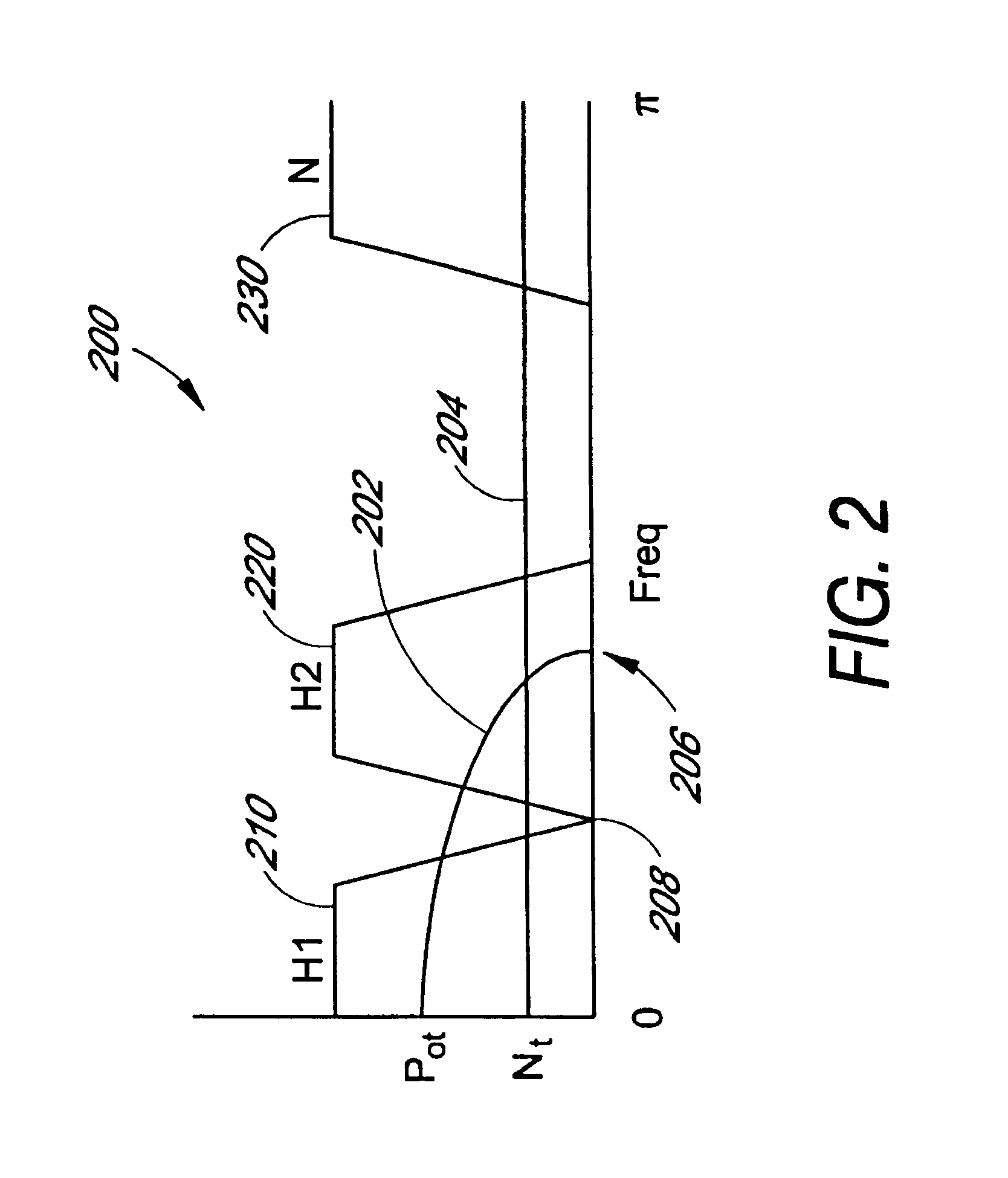
However, when the pilot signal itself is subjected to substantial noise, such as may be caused by fading, multipath interference or loss of signal strength, the ability to precisely determine the pilot signal timing is degraded, impairing its functionality.
Under high-speed conditions, Doppler effects may cause the pilot signal bandwidth to increase beyond a filter bandwidth, resulting in a loss of part of the signal.
The loss of a portion of the pilot signal degrades receiver performance.

Method used


Image

  • Dynamic pilot filter bandwidth estimation
  • Dynamic pilot filter bandwidth estimation
  • Dynamic pilot filter bandwidth estimation

Examples


Embodiment Construction

The aspects, features and advantages of the invention will be better understood by referring to the following detailed description in conjunction with the accompanying drawings. These drawings and the associated description are provided to illustrate embodiments of the invention, and not to limit the scope of the invention.

The following detailed description is directed to certain specific embodiments of the invention. However, the invention can be embodied in a multitude of different ways as defined and covered by the claims. Therefore, the scope of the invention should be determined by reference to the appended claims, and in particular should not be limited to the embodiments described.

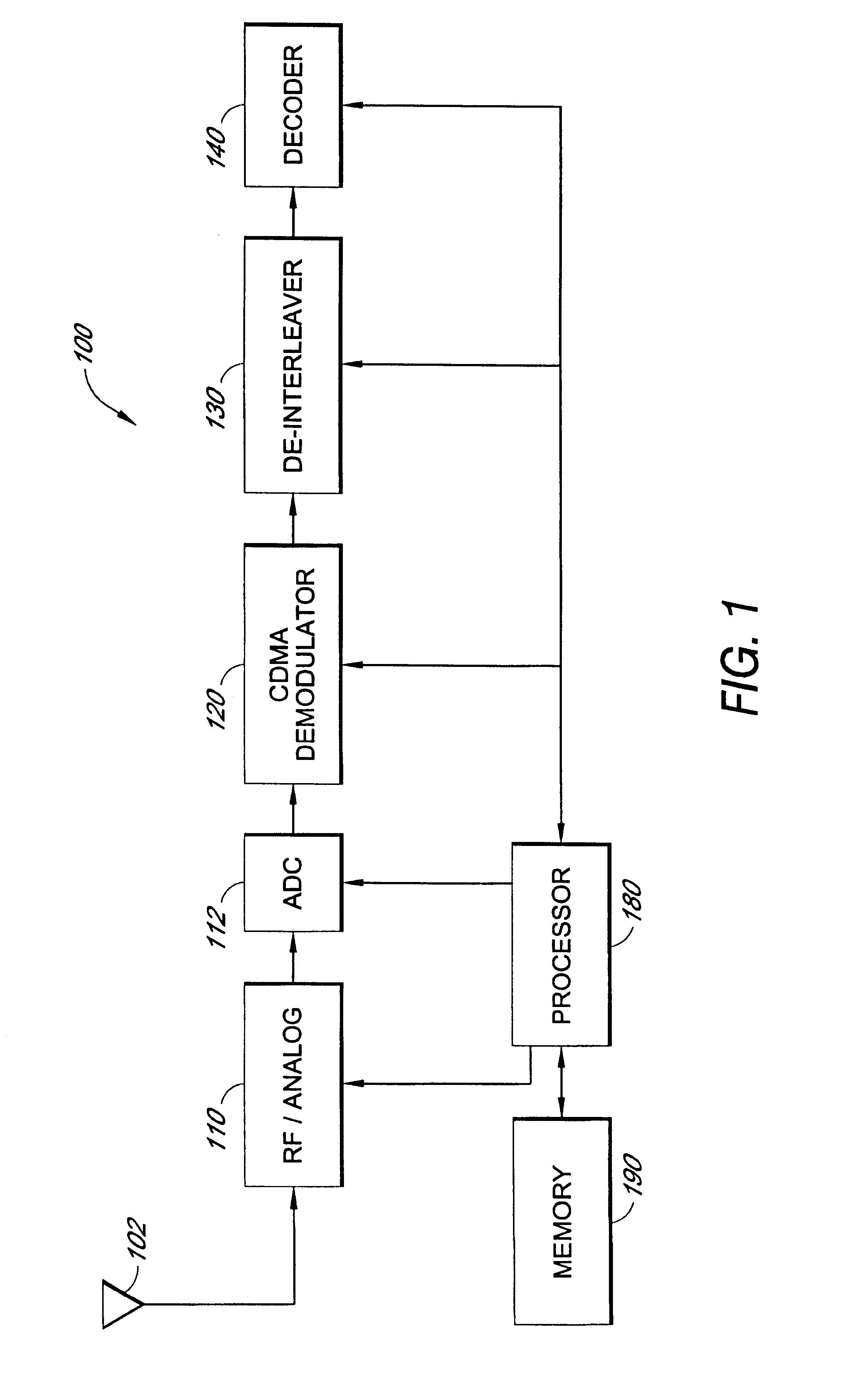
In order to improve the ability to resolve pilot signals, the incoming pilot signal is subjected to filtering to reduce out-of-band noise. However, the bandwidth of the pilot signal varies as a function of the Doppler, fading and multipath effects. As the pilot bandwidth varies, the effectiveness of...


PUM


Abstract

A method and apparatus to dynamically adjust parameters of a filter for a pilot signal. An incoming signal containing a pilot signal is filtered using non-identical filters, and the magnitudes of the filtered signals are compared to estimate a bandwidth of the pilot signal. Noise in the incoming signal may also be estimated, preferably from a portion of the incoming signal not expected to contain the pilot signal. Based on the comparison of the filtered signal magnitudes, which may be compensated to remove the noise contribution, the parameters of a filter applied to the incoming signal to isolate the pilot signal are varied. The parameters may vary the bandwidth of a pilot signal filter. The non-identical filters used in the pilot signal bandwidth estimation may be IIR or FIR filters having different passbands, or may be a correlation of the incoming signal with sinusoids of different frequencies.

Description

1. Field of the InventionThe invention relates to the field of communication devices. More particularly, the invention relates to communication signal recovery.2. Description of the Related ArtCommunication systems that are subject to frequency shifts and multipath interference may employ pilot signals along with information signals, with the pilot signal largely serving as a reference to aid in the precise demodulation of the information. Mobile devices, in particular, may be subject to frequency and phasing shifts caused by Doppler effects, to fading and multipath interference, and a predictable pilot signal may serve to simplify the interpretation of a received signal in the presence of such effects. Accordingly, pilot signals may accompany primary information signals in many communication systems, especially mobile communications systems, and particularly those using spread spectrum Code Division Multiple Access (CDMA) transmission techniques.A CDMA system may be designed to sup...

Claims


Application Information

Patent Timeline
Patent Type & Authority Patents(United States)
IPC IPC(8): H04B1/707H04B1/10H04B1/00
CPCH04B1/707H04B1/7085H04B1/7075H04B1/7097H04B2201/70701
Inventor PATEL, SHIMMANKAN, ANDREW
Owner QUALCOMM INC
Learn More