

Robot teaching apparatus
a robot and teaching technology, applied in the field of robot teaching equipment, can solve the problems of insufficient time and labor, difficult shape input, and insufficient time for inputting the shape model
- Summary
- Abstract
- Description
- Claims
- Application Information
AI Technical Summary
Benefits of technology
Problems solved by technology
Method used
Image

Examples
first embodiment
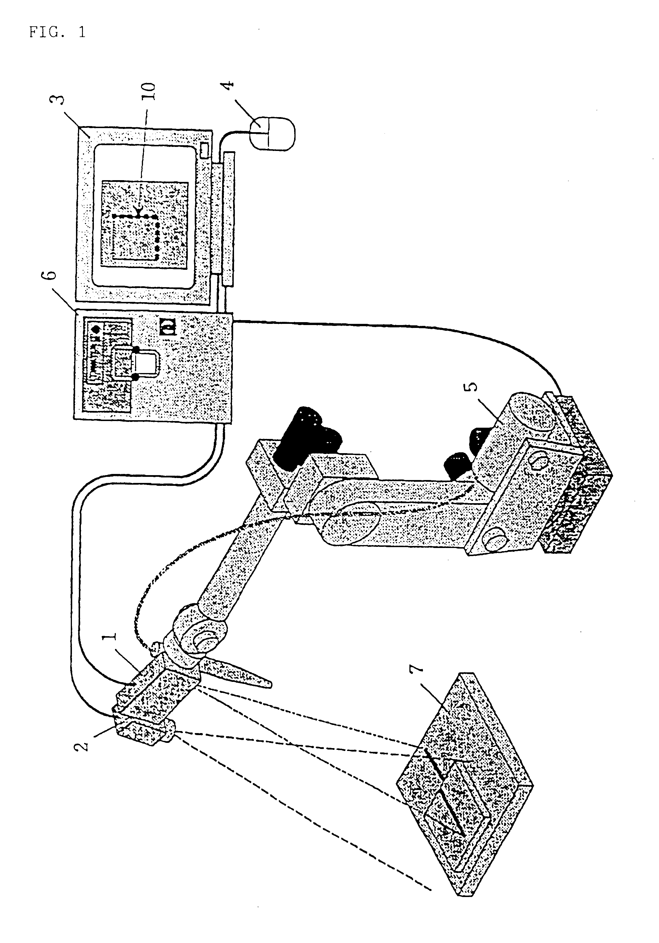
the present invention will be explained with reference to FIG. 1.
Reference numeral 5 denotes a robot which is an object to be taught. Mounted at an arm distal end of the robot 5 are an image pickup device (camera) 2 and a projector 1. The projector 1 has a function for projecting a pattern light. In the embodiment shown in FIG. 1, a slit light projecting type is employed as the projector 1.
A robot controller 6 is of a type that an image processing device is housed therein, and it is connected to the robot 5, the projector 1, the image pickup device 2, a display device 3 and a teaching operation panel (not shown). Provided in this robot controller 6 are not only hardware and software for a normal robot control, but also hardware and software for instructing projecting operations (on / off, a projecting direction, etc.) of the projector 1, and a hardware and a software for photographing the image pickup device 2 or taking-in of photographed images, performing required image processing, ...
second embodiment
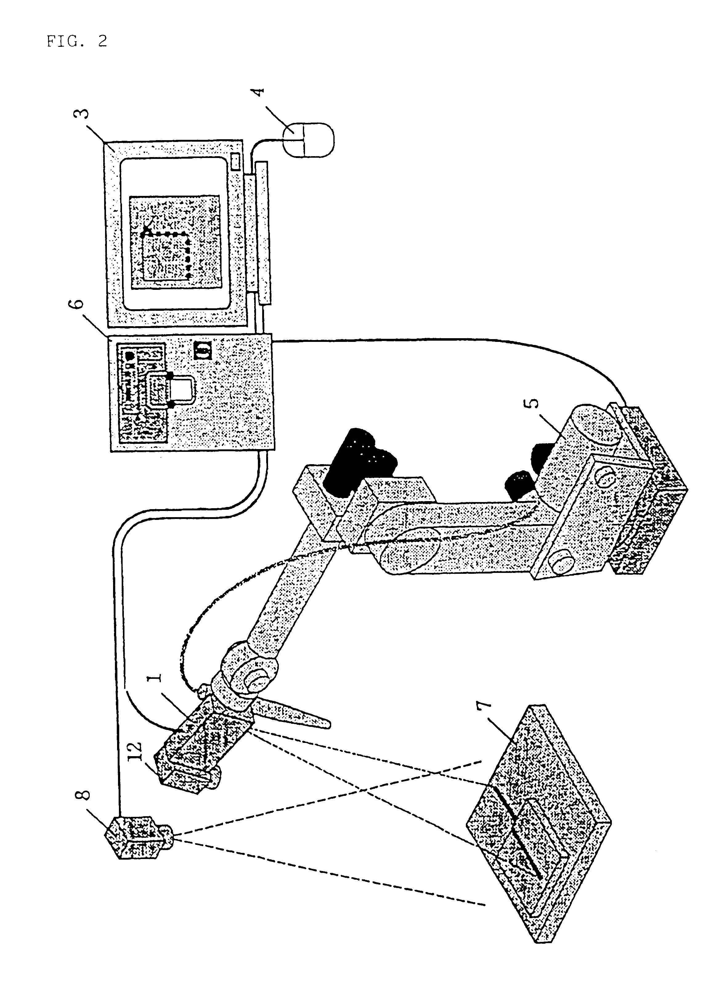
the invention will be explained with reference to FIG. 2.
Mounted at an arm distal end of a robot 5 which is an object to be taught are an image pickup device (camera) 12 and a projector 1. The projector 1 has a function for projecting a pattern light. In the embodiment shown in FIG. 2, a slit light projecting type is employed as the projector 1 in the same manner as the case of the first embodiment (FIG. 1). However, in this embodiment, a fixed camera 8 for photographing a 2-dimensional image, which is arranged so as to overlook a whole working space with a proper distance is utilized as an image pickup device (camera).
A robot controller 6 is of a type that an image processing device is housed therein, and it is connected to the robot 5, the projector 1, the fixed camera 8, a display device 3 and a teaching operation panel (not shown). This robot controller 6 may be similar to that in the first embodiment. A reference work 7 serves as a reference for a teaching work and it is positi...
third embodiment
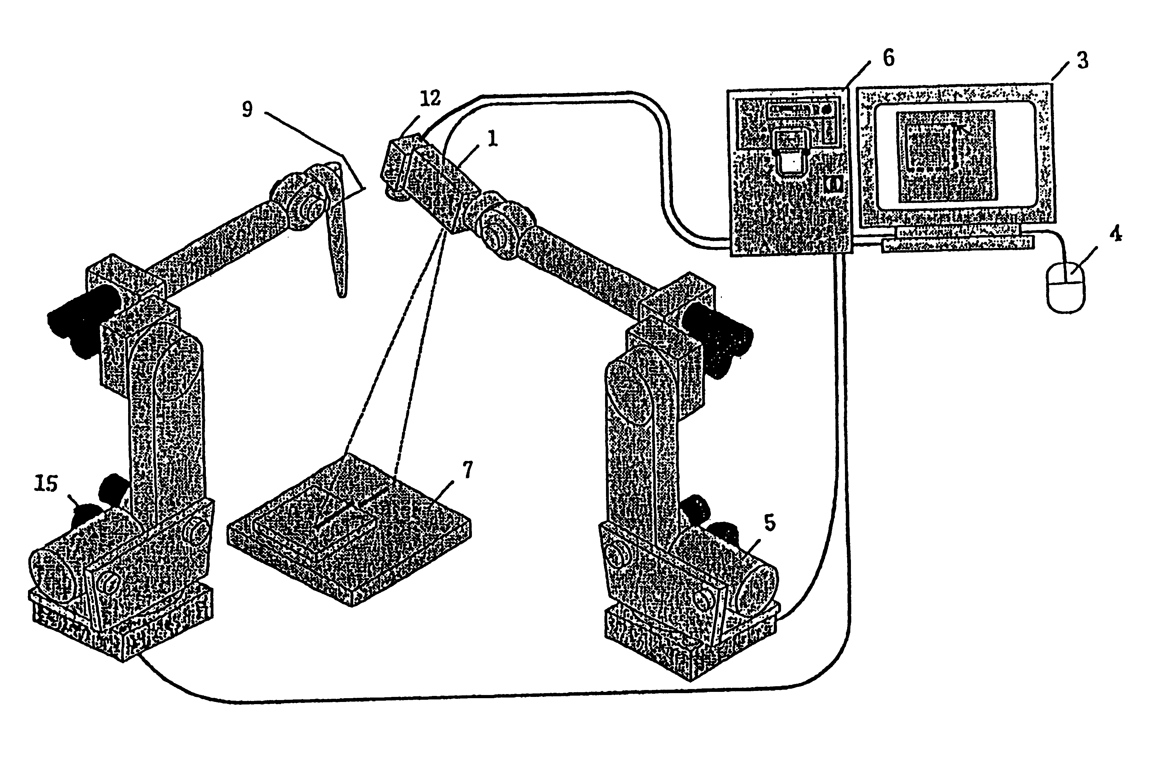
the invention will be explained with reference to FIG. 3.
Mounted at an arm distal end of a robot 5 which is an object to be taught is a projector 1. The projector 1 has a function for projecting a pattern light. In the embodiment shown in FIG. 3, a silt light projecting type is employed as the projector 1 in the same manner as in the cases shown in FIGS. 1 and 2.
In this embodiment, a camera 8 for photographing a 2-dimensional image is mounted at a distal end of an arm of a robot 15 (referred to as a second robot) which is provided in addition to the robot 5 (referred to as a first robot). The second robot 15 constitutes a moving device of a camera 8. The camera 8 mounted on the second robot 15 is utilized for teaching the first robot 5.
A robot controller 6 is of a type that an image processing device is housed therein, and it is connected to the first robot 5, the second robot 15, the projector 1, the camera 8, the display device 3 and the teaching operation panel (not shown).
This r...
PUM
| Property | Measurement | Unit |
|---|---|---|
| Time | aaaaa | aaaaa |
| Shape | aaaaa | aaaaa |
Abstract
Description
Claims
Application Information