Self-centering press-fit connector pin used to secure components to a receiving element

a technology of receiving element and connector pin, which is applied in the direction of connection contact member material, connection connection, fixed connection, etc., can solve the problems of adding to the cost of finished boards, components cannot be placed on boards and then removed,

Inactive Publication Date: 2004-07-20
FOURTE INT SDN BHD
View PDF3 Cites 13 Cited by
  • Summary
  • Abstract
  • Description
  • Claims
  • Application Information

AI Technical Summary

Problems solved by technology

While soldering is the tried and true method of connection for electronic components, the method is quite time consuming and labor intensive, thereby adding to the cost of the finished board.
One major limitation of this connector means is that the component cannot be placed on the board and then removed.

Method used


Image

  • Self-centering press-fit connector pin used to secure components to a receiving element
  • Self-centering press-fit connector pin used to secure components to a receiving element
  • Self-centering press-fit connector pin used to secure components to a receiving element

Examples


Embodiment Construction

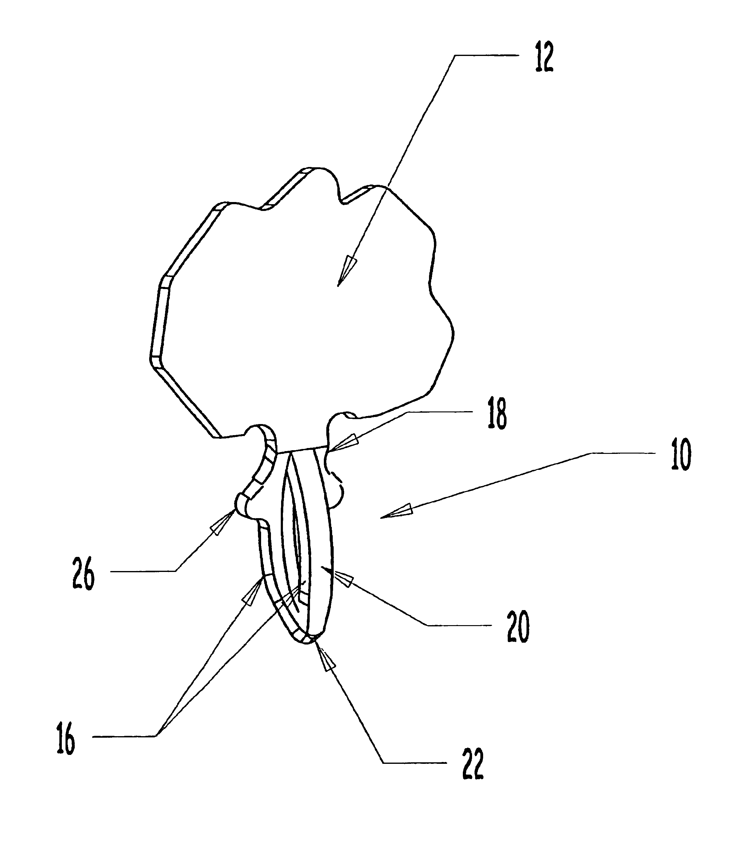
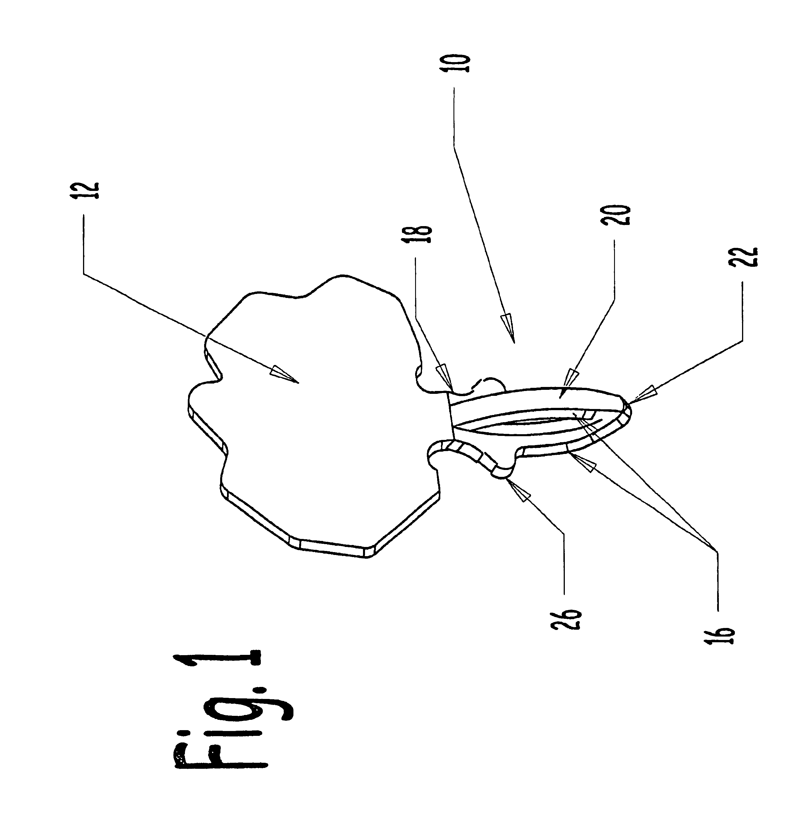
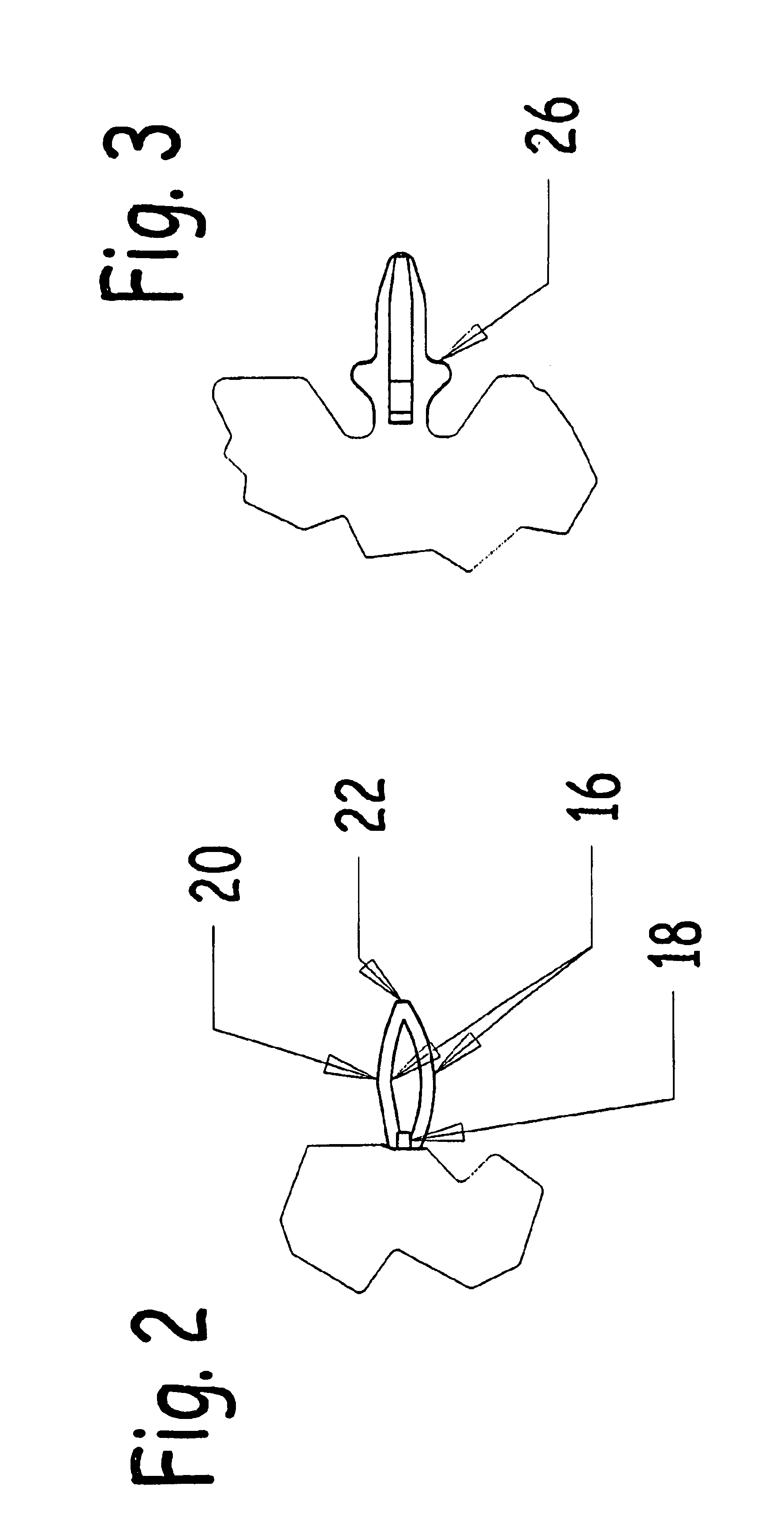
Referring now to FIGS. 5 and 6, a first alternate embodiment of the connector pin 10' of the present invention is formed by successive stamping. The flat blank shown in FIG. 5 is formed into the partially open cylindrical shape illustrated in FIG. 6. The blank includes a pin extension 30 with a widened middle section 34 and a central opening 36.

Following forming, the pin 10' is in the conformation shown in FIG. 6. The central opening 36 is expanded during forming. The middle section 34 is curved into a projection with a circular cross section, the cross section varying from end to end, with a maximum at a midpoint. The curved middle section 34 provides a large contact area for connection with whatever component is being used with the pin 10'. The central opening 36 allows the two connection posts formed from the middle section 34 to flex when the pin 10' is inserted into a receiving board. This ensures a secure connection.

The above disclosure is not intended as limiting. Those skill...


PUM


Abstract

A self-centering press-fit pin that is typically used to secure components to a printed circuit board (PCB). The device includes more than one leg, the legs providing connection points for the component on which the pins are installed. The pin is formed so that the legs act as leaf springs to securely hold the connector in place in the proper installation hole in the board on which the component is installed. The pins are stamped from sheet metal with a progressive die process. By changing the amount of flexion in the legs of the pin, the pressure required to insert the pin into, and remove the pin from, a connection hole can be varied.

Description

1. Field of the InventionThe present invention relates generally to connection means for electronic components, and more particularly is a multiple leg press-fit pin typically used to secure an electronic component to a printed circuit board (PCB).2. Description of the Prior ArtThe manufacture of electronic devices is one of the largest business segments in current day industry. The manufacturing processes used in this area are therefore the subject of much interest in the technology community. The present invention is directed generally to the area of PCB assembly.Current art usually requires that components be soldered to the board on which the components are to be installed. This connection method is used on the vast majority of electronic components. While soldering is the tried and true method of connection for electronic components, the method is quite time consuming and labor intensive, thereby adding to the cost of the finished board.One alternative method of connection of t...

Claims


Application Information

Patent Timeline
Patent Type & Authority Patents(United States)
IPC IPC(8): H05K3/30H01R12/57
CPCH01R12/585H05K3/308H05K2201/10371H05K2201/10856
Inventor FAJARDO, IGGONI
Owner FOURTE INT SDN BHD
Why Eureka
Try Eureka