Closed cable drag chain

a drag chain and cable technology, applied in the direction of cables, cable arrangement between relatively moving parts, coupling device connections, etc., can solve the problems of damage to a cable or a hose, and disordered outward appearance of the cable or hos

Inactive Publication Date: 2004-08-10
TSUBAKIMOTO CHAIN CO
View PDF14 Cites 77 Cited by
  • Summary
  • Abstract
  • Description
  • Claims
  • Application Information

AI Technical Summary

Problems solved by technology

When a cable or a hydraulic or pneumatic hose is connected to a mobile device such as a machine tool, a civil engineering machinery, a transfer system or the like, undue torsion or tension is generated in the cable or hose by its movement thereby damaging a cable or a hose and disordering its outward appearance.

Method used


Image

  • Closed cable drag chain
  • Closed cable drag chain
  • Closed cable drag chain

Examples


Embodiment Construction

Description of Reference Numerals

10 . . . Intermediate frame

11 . . . Intermediate frame body

11a . . . Cable holding groove

11b . . . Lower open end surface

11e . . . Upper open end surface

11d . . . Side wall engagement portion

11e . . . Step portion

11f . . . Connecting pin portion

11g . . . Pin hole portion

11h . . . Fitting groove

12 . . . Opening / closing lid member

12a . . . Locking arm

12b . . . Bend limiting end portion

12c . . . Engagement portion

20 . . . Outer frame

21 . . . Upper outer frame

22 . . . Lower outer frame

23 . . . Snap locking portion

24 . . . Hinge portion

25 . . . Elastic sealed portion

26 . . . Engagement piece

26a . . . Engagement hole

C . . . Cable or the like

S . . . Coup ling gap

Embodiments of the Invention

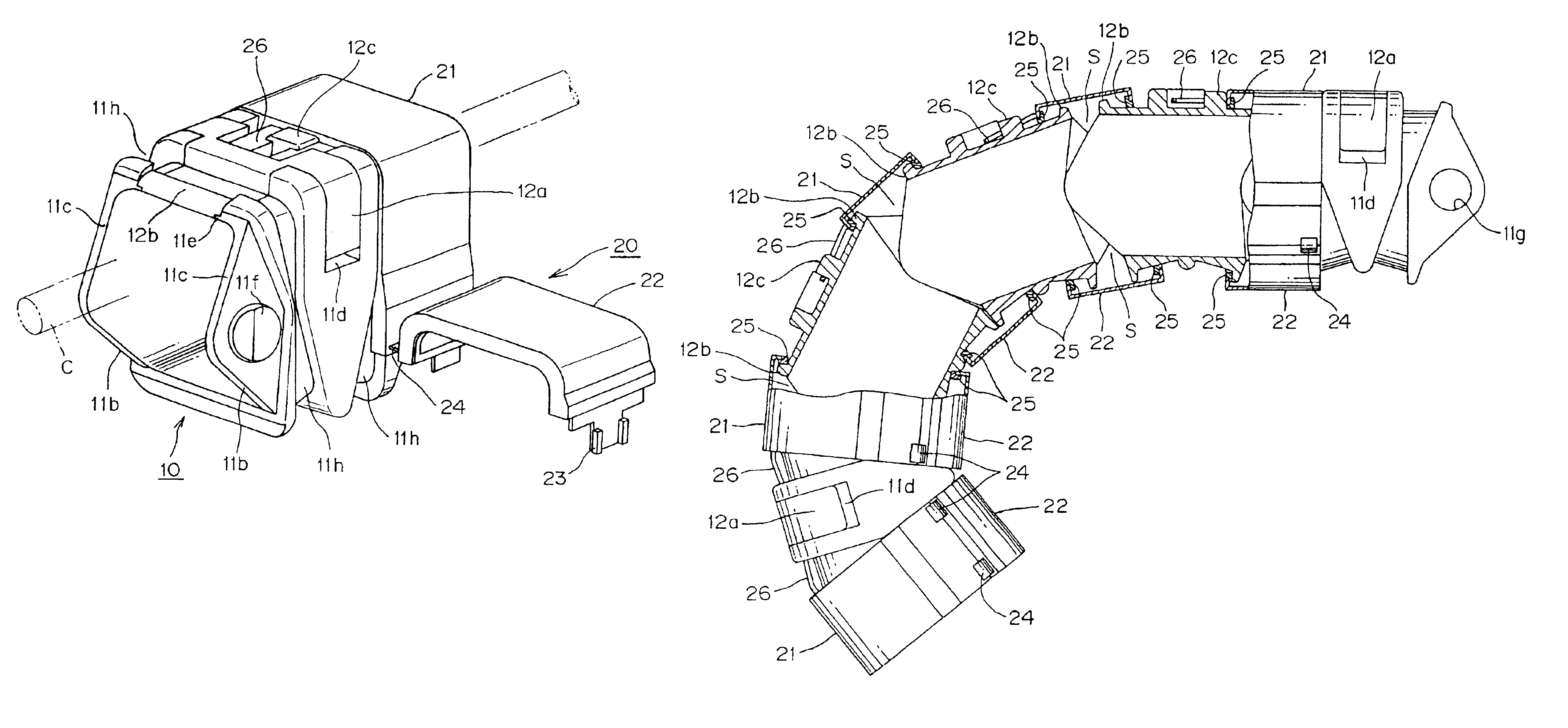
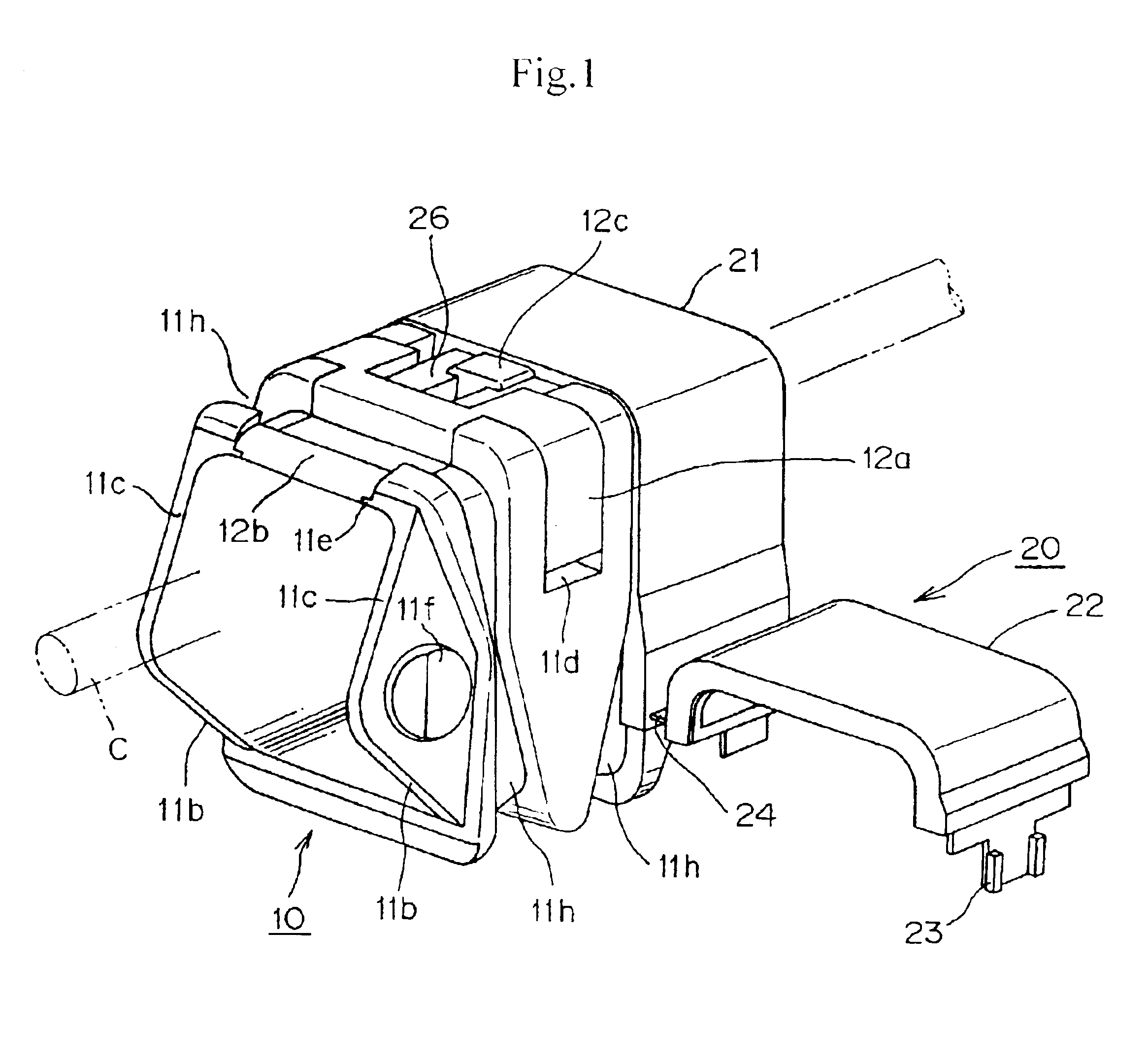
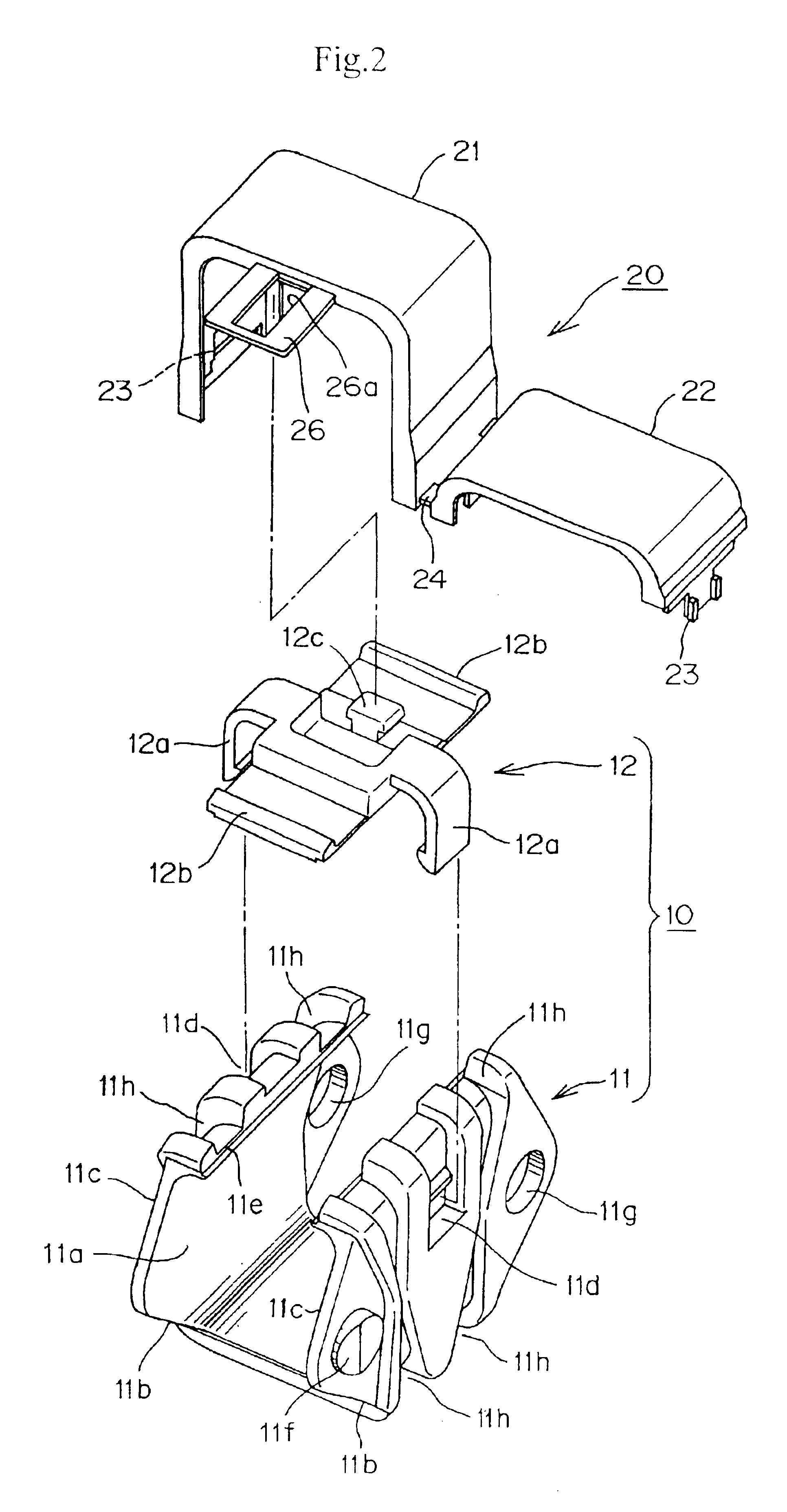
One Example of a closed cable drag chain preferable as the present invention will be described with reference to FIGS. 1 and 3. FIG. 1 is an enlarged perspective view of a configuration unit of a closed cable drag chain, which is one Example of the present invention, FIG....


PUM


Abstract

To provide a closed cable drag chain, which is capable of preventing the contact wear powder generated in holding and guiding the cable or the like from being scattered by reliably closing the cable or the like, and wherein the assembling, maintenance and repair are easy while having light weight and low noise. In a closed cable drag chain into which a cable or the like is inserted to be held and guided in conditions where a number of intermediate frames (10) are articulately connected to each other, an outer frame (20) including a removable opening / closing frame structure fit-covers a coupling portion of the adjacent intermediate frames (10) to close the coupling gaps S respectively thereby coupling it in a tubular shape, the intermediate frame (10) comprises an intermediate frame body and an opening / closing lid member (12) fitted into the intermediate frame body (11), and the intermediate frame body (11) includes lower open end surfaces (11b), which abut with each other on the chain bend inner peripheral side to hold a required bending position of the chain and upper open end surfaces (11c), which abut with each other on the chain bend outer peripheral side to hold a straight extended position of the chain.

Description

The present invention relates to a technical field of a cable drag chain, which holds and guides an electric cable or a hydraulic or pneumatic hose between a mobile portion where a machine tool, a civil engineering machinery, a transfer system or the like is moved and a fixed portion.RELATED ARTWhen a cable or a hydraulic or pneumatic hose is connected to a mobile device such as a machine tool, a civil engineering machinery, a transfer system or the like, undue torsion or tension is generated in the cable or hose by its movement thereby damaging a cable or a hose and disordering its outward appearance. Therefore, a cable drag chain for holding and guiding the cable or hose has been proposed.A support device for a cable or a hose, which was proposed in Japanese Examined Patent Publication No. Sho. 62-15008 for example, includes a plastic small-diameter tube member provided with a fan-shaped groove in upward and downward directions of an outer peripheral surface of its side, inside th...

Claims


Application Information

Patent Timeline
Patent Type & Authority Patents(United States)
IPC IPC(8): F16G13/16F16G13/00H02G11/00H02G3/04H02G3/30
CPCF16G13/16H02G11/006
Inventor KOMIYA, SHOICHIRO
Owner TSUBAKIMOTO CHAIN CO
Why Eureka
Try Eureka