Multiple, parallel filament lamp

a filament lamp and parallel technology, applied in the field of lamps, can solve the problems of tungsten molecules evaporating off of the filament and condense onto the glass bulb, further evaporation, and filament portion becoming hotter, etc., to prolong the usable increase the life of the lamp, and high visible light emission efficiency

Inactive Publication Date: 2004-08-10
BEST POINT GROUP
View PDF25 Cites 12 Cited by
  • Summary
  • Abstract
  • Description
  • Claims
  • Application Information

AI Technical Summary

Benefits of technology

A feature of the present invention is the use of at least one backup (or secondary) filament segment. When the primary filament segment to which the backup (or secondary) filament segment burns out, the light will continue to operate by using the backup (or secondary) filament segment in place of the failed primary filament segment. Not only does the backup (or secondary) filament segment extend the usable life of the lamp, but, through the use of a number of groups, segments and/or backups, e.g., tertiary filament segments acting as second-level backups to backup (or secondary) filament segments, etc., the life of the lamp may be increased by a factor much greater than two while still maintaining high visible light emission efficiency. Generally, visible light emission efficiency is exchanged for long-life in most current "long-life" lamps. Related to this, the increased lifetime also reduces the time and cost of changing light bulbs by the same factor. Therefore, even allowing for a

Problems solved by technology

Also, these high temperatures cause some of the tungsten molecules to evaporate off of the filament and condense onto the glass bulb.
This causes the filament to become thinner and more resistant to current flow, causing the thinner filament portion to become even hotter, and leading to further evaporation.
Similarly, fabrication inefficiencies can also cause thin spots to be formed on the filament during manufacturing.
Since the amount of time that

Method used


Image

  • Multiple, parallel filament lamp
  • Multiple, parallel filament lamp
  • Multiple, parallel filament lamp

Examples


Embodiment Construction

accompanied by the following drawings.

BRIEF DESCRIPTION OF THE SEVERAL VIEWS OF THE DRAWINGS

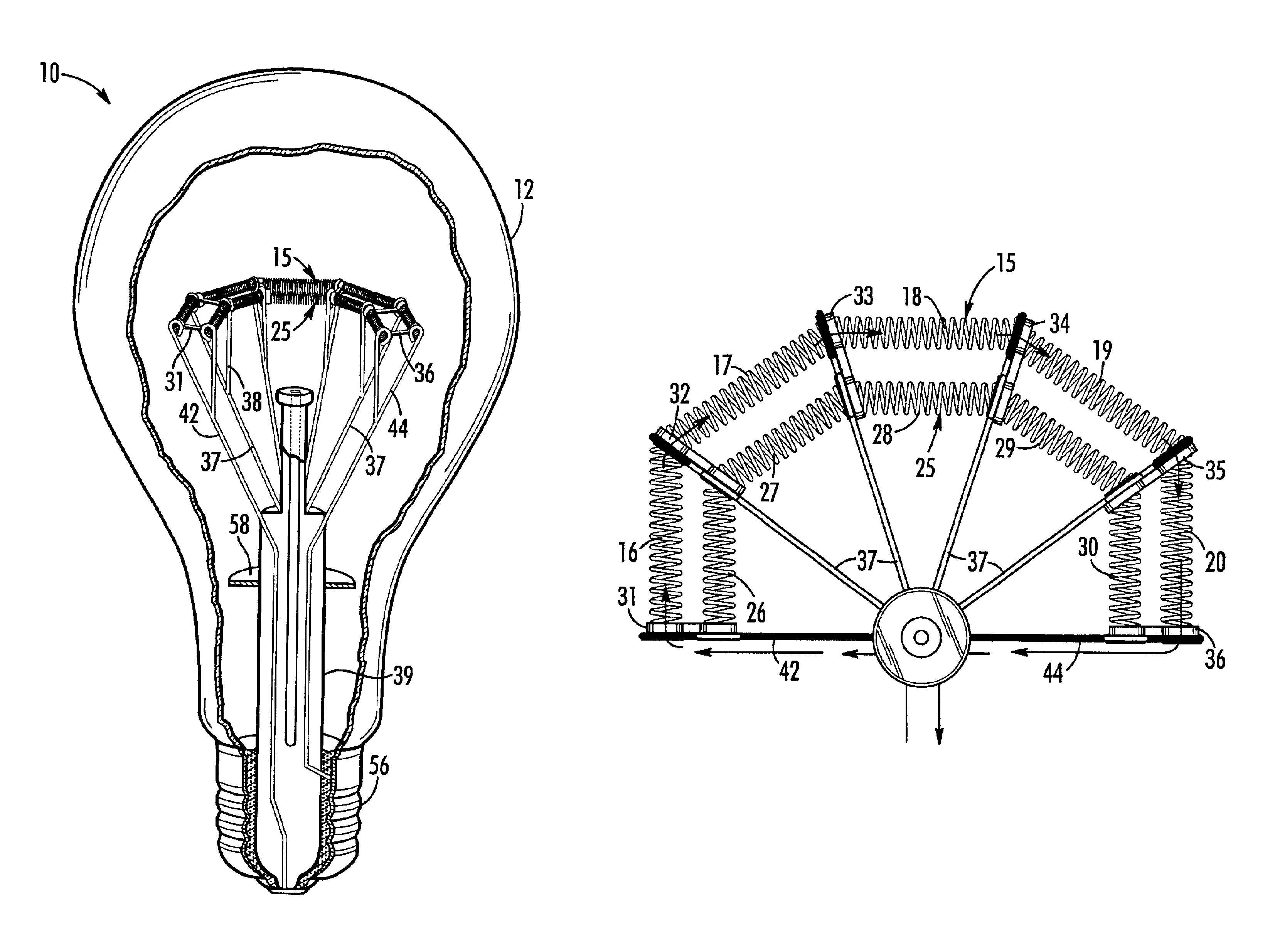
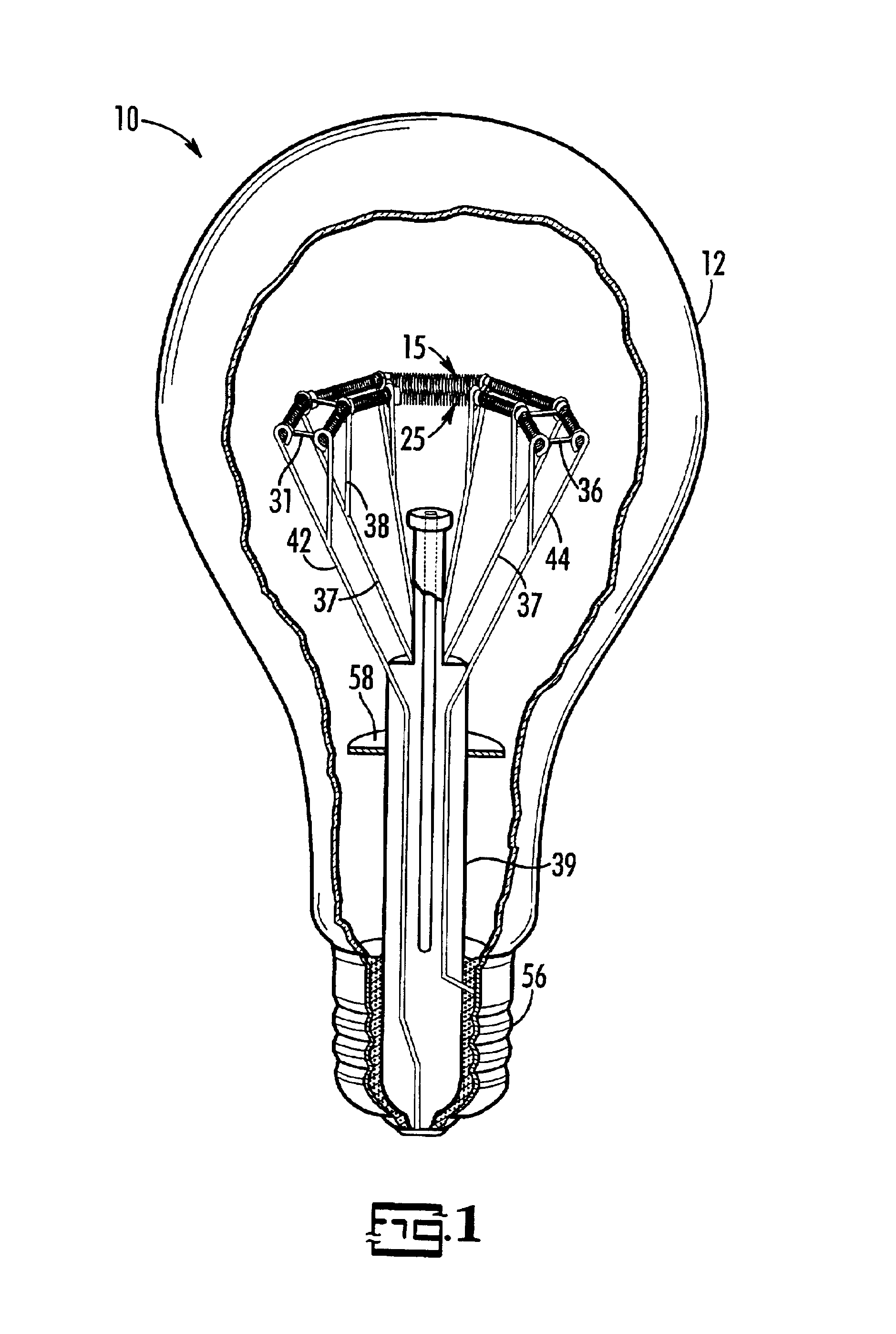
FIG. 1 is a perspective cut away view of the present invention lamp.

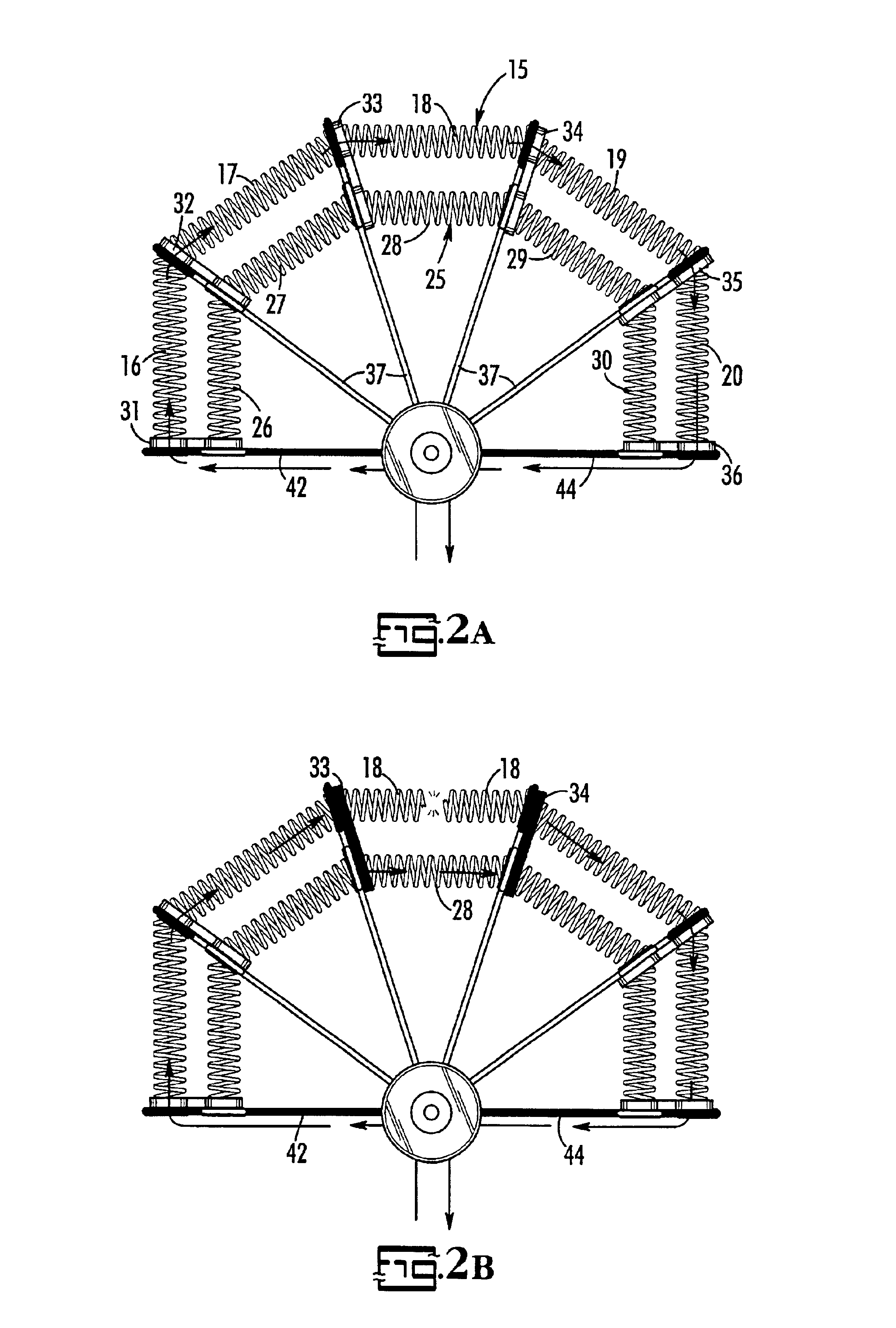
FIG. 2A is a plan view of a dual filament group embodiment of the present invention showing the current flow path during normal operation of all primary-group filaments, according to a preferred embodiment of the present invention.

FIG. 2B is a plan view of the dual filament group embodiment shown in FIG. 2A showing an example of the current flow path during normal operation of a backup filament segment bypassing an open circuited primary filament segment.

FIG. 3 is a perspective cut away view of another preferred embodiment of the present invention lamp.

DETAILED DESCRIPTION OF THE INVENTION

The present invention is an improvement to electric lamps that is primarily directed, but not limited, to extending an incandescent lamp's lifetime. In particular, the improvement includes the use of backup filaments (or filament segments) t...


PUM


Abstract

An improvement to the usable lifetime of a lamp includes the use of a primary filament, a backup filament, and a means to switch portions of the backup filament into the current flow path after a portion of the primary filament open circuits. Using bypass shunts, which do not become electrically conductive until a portion of the primary filament open circuits, an open circuited portion of the primary filament can be electrically replaced with an associated backup filament portion to keep the lamp lit. The shunts in one embodiment are made of oxidized wire and are wrapped around the primary and backup filaments, in a spaced-apart relation, forming filament pairs consisting of a primary filament segment and its associated backup filament segment. In another embodiment, support brackets are used to not only support the primary and backup filaments, but are also used to provide the bypass shunt function as well.

Description

CROSS REFERENCE TO RELATED APPLICATIONSNot ApplicableSTATEMENT REGARDING FEDERALLY SPONSORED RESEARCH OR DEVELOPMENTNot applicable.REFERENCE TO A SEQUENCE LISTING, A TABLE, OR A COMPUTER PROGRAM LISTING COMPACT DISK APPENDIXNot Applicable.BACKGROUND OF THE INVENTIONThe present invention relates to lamps. More particularly, the present invention relates to multi-filament lamps. Generally, inside the glass envelope or bulb of a lamp, a filament, which is usually made from tungsten, is extended between two power terminals. Basically, the filament is a resistor that heats up when a voltage is applied across the terminals, and normally operates at temperatures of about 2500.degree. C. in incandescent lamps, and at significantly higher temperatures in halogen lamps. At these high temperatures the filament gives off a substantial amount of thermal radiation, which includes a considerable amount of visible light (when compared to the amount of visible light given off at lower operating temp...

Claims


Application Information

Patent Timeline
IPC IPC(8): H01J5/00H01J5/48H01J5/50H01K9/00H01J1/88H01J1/00H01K1/18H01J19/00H01K1/00H01J19/42H01K1/14H01K1/16H01K1/64H01K1/70
CPCH01K1/14H01K1/16H01K1/18H01K1/64H01K1/70
Inventor GIBBONEY, JR., JAMES W
Owner BEST POINT GROUP
Why Eureka
Try Eureka