
Method and arrangement for transmitting and receiving encoded images

a technology of encoded images and transmission methods, applied in the direction of selective content distribution, signal generators with optical-mechanical scanning, television systems, etc., can solve the problems of insufficient bandwidth of the system (one or few lines of vertical blanking interval) to transmit all subtitles in real time, and more complex data service systems such as teleweb are being developed

Inactive Publication Date: 2004-08-10
KONINKLIJKE PHILIPS ELECTRONICS NV
View PDF25 Cites 23 Cited by
  • Summary
  • Abstract
  • Description
  • Claims
  • Application Information

AI Technical Summary

Benefits of technology

It should be noted that advance transmission of subtitles with time stamps is known per se from International Patent Application WO 96 / 19077. In this prior-art system, the subtitles are transmitted along with a compressed digital video signal. Digital video signals already include a reference clock. Digital television receivers comprise an input buffer in which the compressed video signal is buffered in order to compensate for the varying amounts of frame data. The encoded video frames include time stamps representing the time at which they have to be removed from the buffer and / or displayed, so that the buffer does not overflow or underflow. The transmitted reference clock thus controls the video display timing. As the time stamps in subtitle images relate to the same reference clock, the subtitles can exactly be synchronized with given frames of the video signal.

Problems solved by technology

More complex data service systems such as TeleWeb are currently being developed.
The unknown delay of a TeleWeb subtitle image poses a problem in that synchronization between a television program and its subtitling is difficult to achieve.
The bandwidth of the system (one or few lines of the vertical blanking interval) is not sufficient to transmit all subtitles in real time.

Method used


Image

  • Method and arrangement for transmitting and receiving encoded images
  • Method and arrangement for transmitting and receiving encoded images
  • Method and arrangement for transmitting and receiving encoded images

Examples


Embodiment Construction

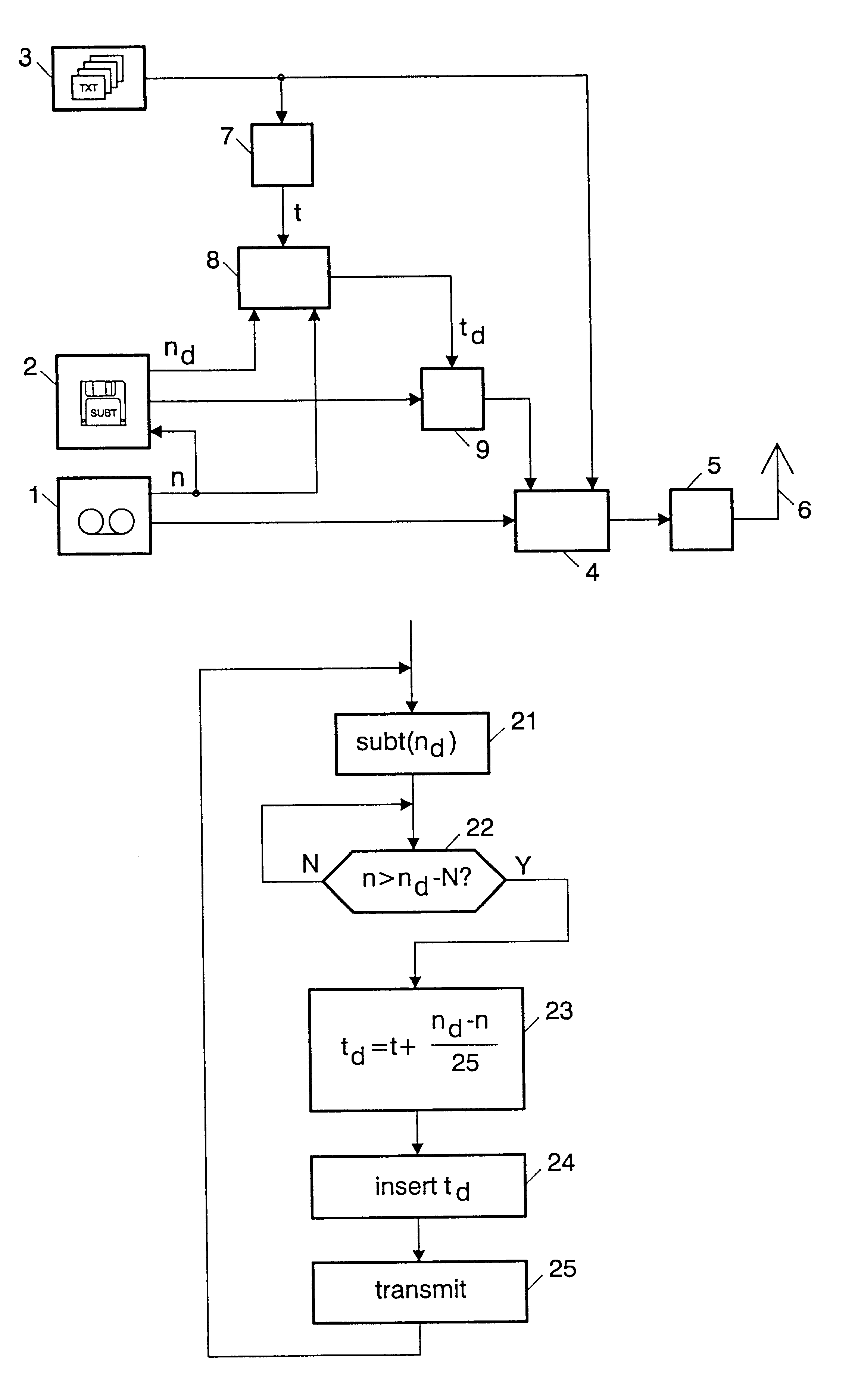
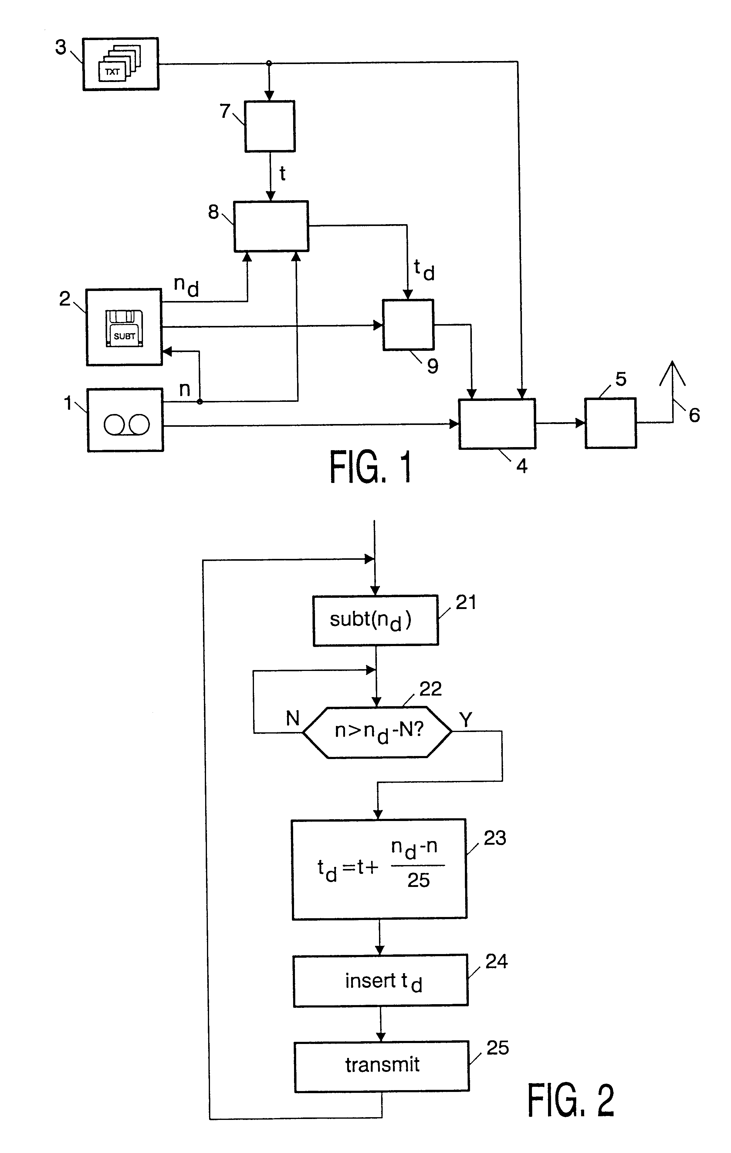
FIG. 1 shows a schematic diagram of a transmitter in accordance with the invention. It will be assumed that the television program being broadcast is a prerecorded program, i.e. the content is being played back from a video recorder 1. The video frames of the recorded television signal are consecutively numbered. The video recorder outputs the current video frame number n at a second output.

The subtitles associated with the television program have been prepared in advance. They are stored in the form of encoded images on a subtitling computer system 2. The computer also stores for each subtitle image the frame number n.sub.d of the video frame at which the subtitle is to be reproduced. The subtitling computer 2 receives the current frame number n from the video recorder 1.

The transmitter further comprises a conventional teletext source 3, which generates a cyclic sequence of teletext pages. The conventional teletext service includes transmission of a real time clock. As is generally...


PUM


Abstract

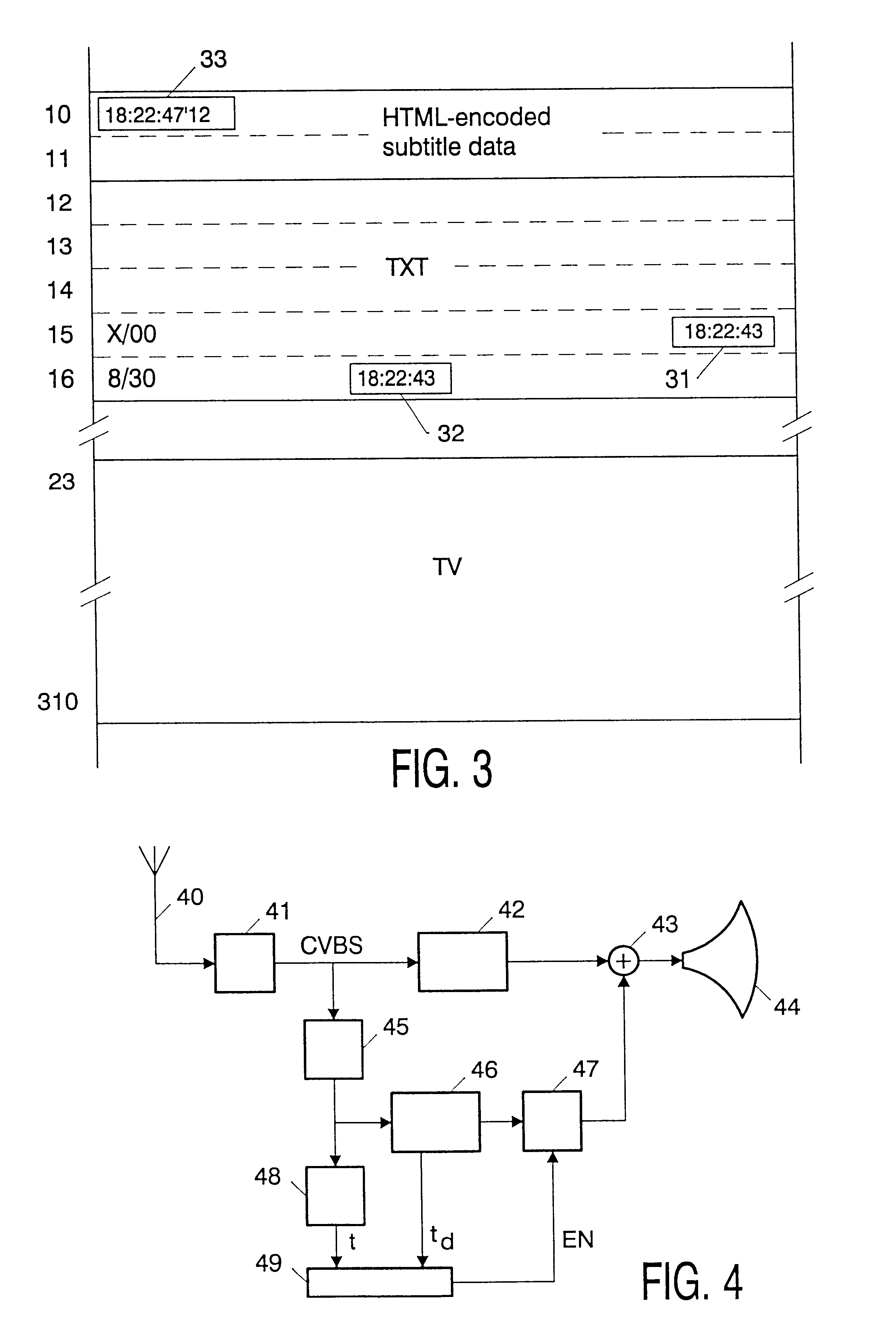
TeleWeb services are currently being developed, in which HTML-encoded images are transmitted in the vertical blanking interval of a conventional analog television signal. For special applications, such as subtitling and targeted advertising, the relevant TeleWeb images must be displayed substantially in synchronism with given video frames of the television signal. This is achieved by transmitting the encoded images in advance and provide them with a time stamp (33) which specifies the display time in terms of a reference clock. The reference clock is preferably derived from the teletext clock time (31,32). A possible display time stamp format is hh:mm:ss'ff, where ff specifies a frame within a second. At the receiver end, the teletext clock is interpolated to reconstruct the reference clock, and the subtitles are buffered until the display time stamp matches the actual clock time.

Description

The invention relates to methods of transmitting encoded images in inactive video periods of an analog (i.e. PAL, NTSC, etc.) television signal and reproducing said images in synchronism with given frames of the television signal.A known method of transmitting encoded images in inactive video periods of an analog television signal for reproduction in synchronism with given frames of the television signal is provided by World System Teletext. Teletext, standardized in the early 70s, provides the facility to transmit subtitle pages along with other teletext pages in the vertical blanking interval of the television signal. The subtitles are transmitted in synchronism with the video scene. That is, each subtitle page is inserted in the teletext stream precisely at the time it is to be reproduced. Since teletext information is decoded in real time, the subtitle page is displayed without any delay.More complex data service systems such as TeleWeb are currently being developed. TeleWeb ima...

Claims


Application Information

Patent Timeline
IPC IPC(8): H04N7/087H04N7/088H04N5/04H04N5/46H04N5/445H04N7/08H04N7/081H04N7/083
CPCH04N5/04H04N7/0882H04N7/0885H04N5/46H04N21/4884H04N21/4305H04N21/435H04N21/4888H04N21/8547H04N7/087
Inventor VAN GESTEL, HENRICUS ANTONIUS WILHELMUS
Owner KONINKLIJKE PHILIPS ELECTRONICS NV
Learn More