Removable insert for a binder

a binder and insert technology, applied in the field of spiral and other ring-type binders, can solve the problems of only being able to place inserts within ring-type binders with separable page retaining members, and removing inserts, and achieve the effect of convenient inserting

Inactive Publication Date: 2004-08-17
ROCA PRODIONS
View PDF24 Cites 14 Cited by
  • Summary
  • Abstract
  • Description
  • Claims
  • Application Information

AI Technical Summary

Benefits of technology

It is a further object of the present invention to disclose and provide such a removable insert which can be inserted into all types of ring-type binders without requiring any difficult manipulation thereof.
It is also an object of the present invention to disclose and provide such a removable insert which can be manufactured at a low cost.
Advantageously, a removable insert in accordance with the present invention may be easily inserted into all types of ring-type binders, e.g., 3-ring or double spiral ring binders. The insert generally comprises a thin body and a first page retaining member and a fastener. The thin body typically has a thickness of about between 0.015 and 0.030 inches. However, the thin body may have a thickness of up to 0.0625 inches in some circumstances. Moreover, the thin body may be a paper page as thin as 0.003 inches having reinforcements.

Problems solved by technology

However, there are several problems with these removable inserts.
First of all, such inserts can only be used with ring-type binders having separable page retaining members.
Secondly, the placement of such inserts within such ring-type binders can only be accomplished after considerable manipulation of both the binder and the insert.
Thus, it is seen that such removable inserts are not easily used by the operator.
Additionally, it is seen that such removable inserts are not insertable into spiral or other ring-type binders wherein the page retaining members are not configured for insertion or removal of loose-leaf elements.

Method used


Image

  • Removable insert for a binder
  • Removable insert for a binder
  • Removable insert for a binder

Examples


Embodiment Construction

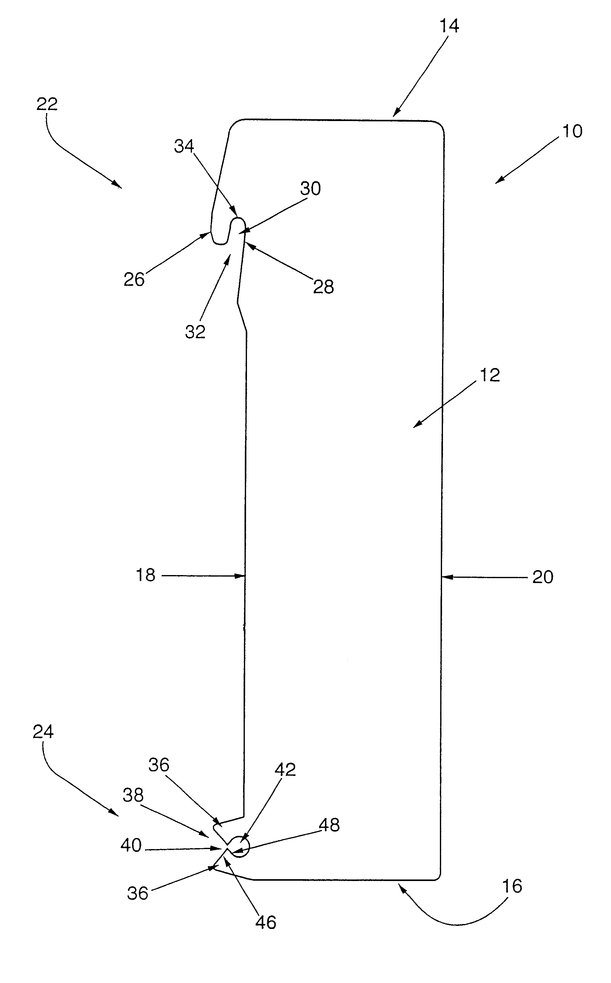
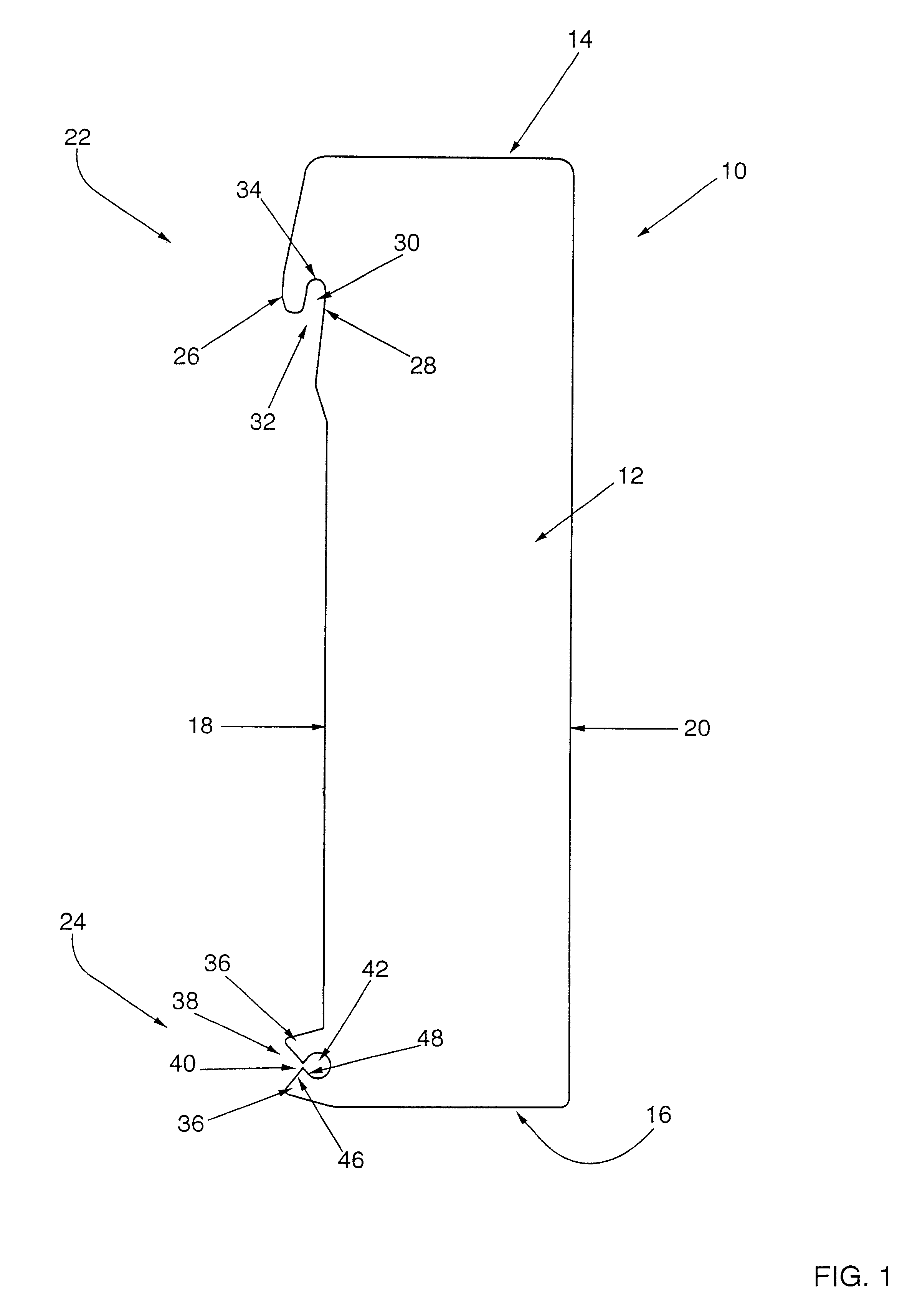
A first preferred exemplary embodiment of a removable insert in accordance with the present invention is shown generally at 10 in FIGS. 1-2. Referring initially to FIG. 1, the removable insert includes a thin body member 12 having first and second ends 14 and 16 and longitudinal edges 18 and 20 extending therebetweeen. The removable insert includes a hooking element 22 disposed towards the first end 14 and a fastener 24 disposed towards the second end 16, each of which extend laterally from longitudinal edge 18.

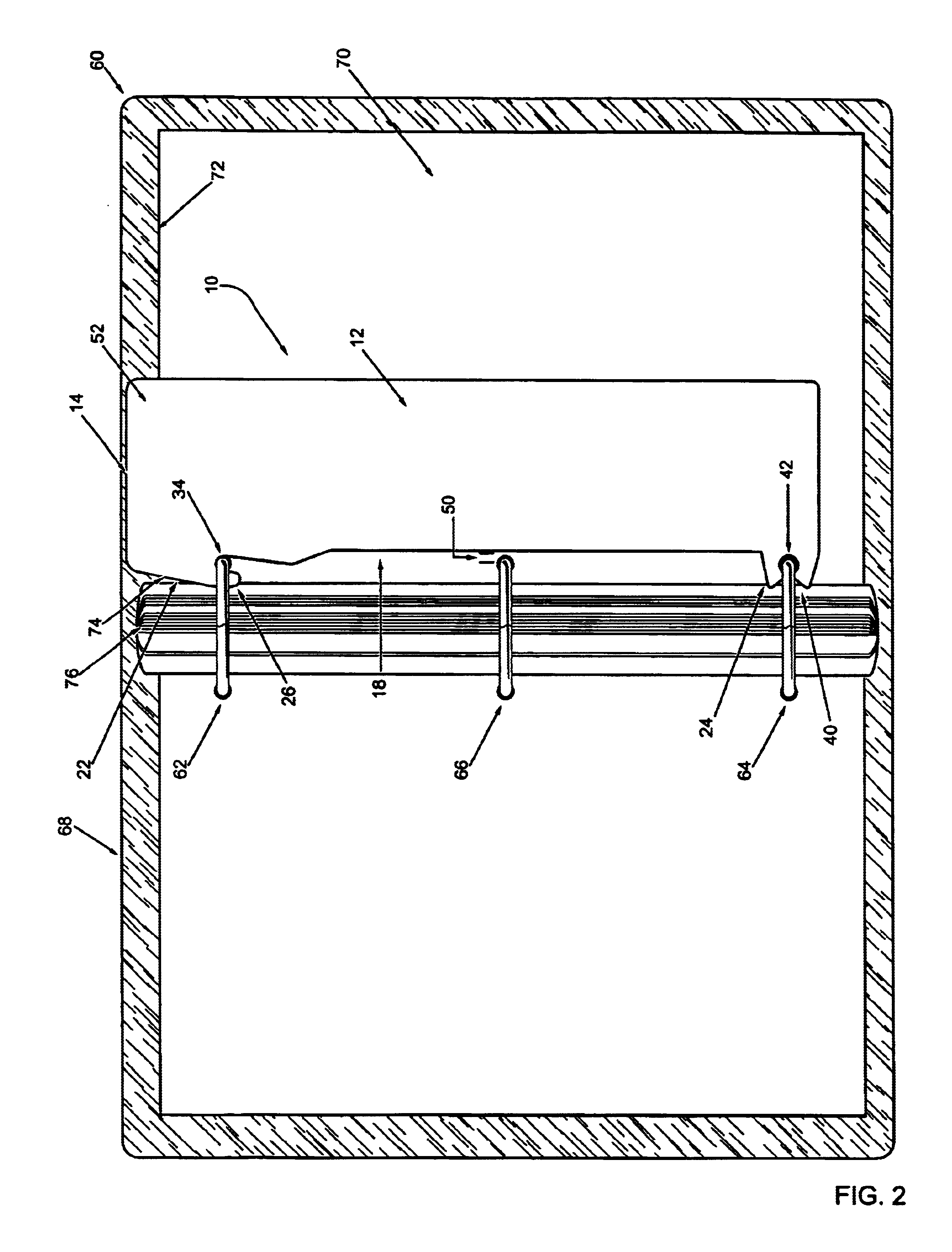
The hooking element 22 includes a downwardly extending arm 26 which, together with portion 28 of longitudinal edge 18, defines longitudinal extending recess 30. Longitudinally extending recess 30 includes a divergent opening 32 for receiving a first page retaining member such as shown at 62 in FIG. 2. Recess 30 also includes an arcuate journal bearing 34 which limits the downward movement of the insert when the hooking element 22 is positioned over a first page retaining memb...


PUM

PropertyMeasurementUnit
thicknessaaaaaaaaaa
thicknessaaaaaaaaaa
thicknessaaaaaaaaaa

Abstract

A removable insert adapted for use with a spiral or other ring-type binder includes a thin body member, a hooking element connected to, or integral with, the body member which defines a longitudinally extending recess configured to receive at least a first page retaining member, and a fastener connected to, or integral with, the body member configured to detachably secure the body member to a second page retaining member. The hooking element includes a journal bearing about which the first page retaining member may be rotated. The fastener includes a constricted channel adjacent to the edge of the insert and an enlarged portion disposed inwardly from the edge.

Description

I. FIELD OF THE INVENTIONThe present invention relates generally to spiral and other ring-type binders and more particularly to bookmarks, rulers, post-it holders, paper pages and other apparatus configured for removable insertion in spiral or other ring-type binders.II. BACKGROUND OF THE INVENTIONA great many spiral and other ring-type binders have been developed for retaining a plurality of separate pages or other loose-leaf elements therein. These ring-type binders typically include a plurality of loose-leaf page retaining members positioned longitudinally between opposing ends of such binders. The page retaining members are configured to extend through corresponding apertures in the preferred loose-leaf elements thereby retaining the loose-leaf elements in the ring-type binder.In some ring-type binders, the page retaining members include two separable members which, then adjoined, form a loop for retaining loose-leaf elements. These separable page retaining members are configure...

Claims


Application Information

Patent Timeline
Patent Type & Authority Patents(United States)
IPC IPC(8): B42D9/00B42F13/00
CPCB42D9/001B42F3/003B42F13/0006Y10T24/3449
Inventor ROCA, ROBERT JOHN
Owner ROCA PRODIONS
Why Eureka
Try Eureka