Viewfinder optical system and optical apparatus
a technology of optical system and optical apparatus, applied in the field of viewfinder optical system, can solve the problems of difficult observation disadvantage of conventional viewfinder optical system, and difficulty in observing good viewfinder image, and achieve the effect of good viewfinder imag
- Summary
- Abstract
- Description
- Claims
- Application Information
AI Technical Summary
Benefits of technology
Problems solved by technology
Method used
Image
Examples
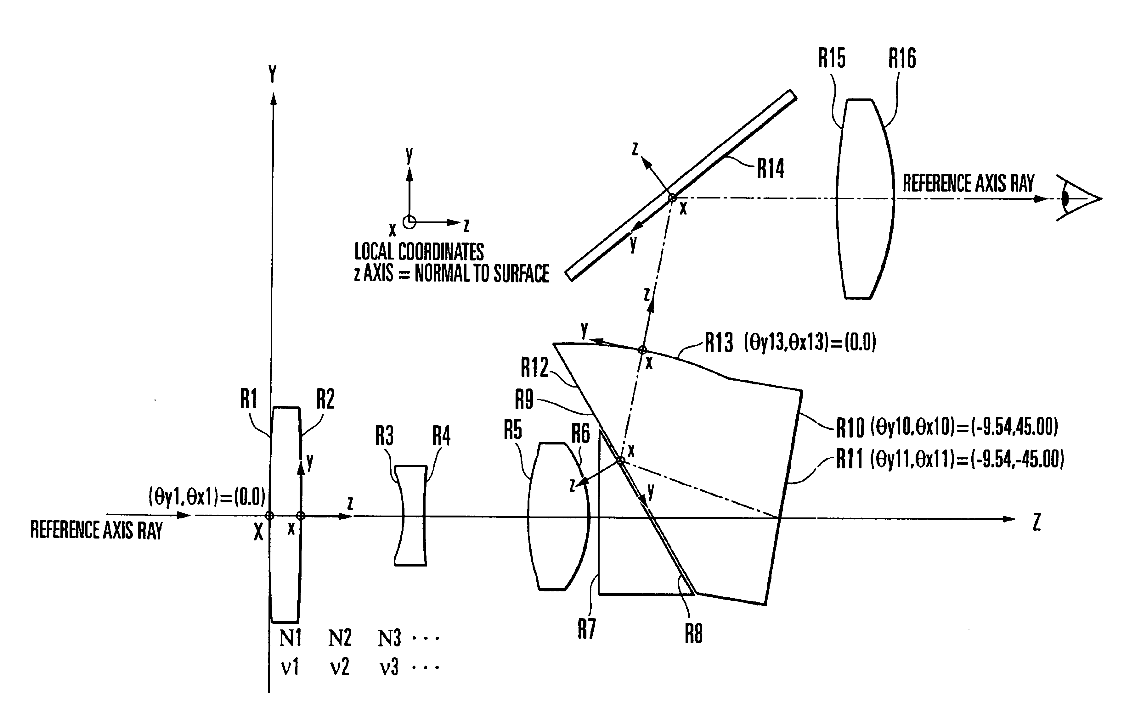
numerical example 2
2.omega.=48.7.degree.-28.4.degree..gamma.=0.47-0.84
Variable Separation According to Focal Length
Shape of Rotationally-symmetrical Aspheric Surface
Shape of Rotationally-asymmetrical Aspheric Surface
Next, ninth to thirteenth embodiments of the invention are described with reference to FIGS. 22 to 27.
ninth embodiment
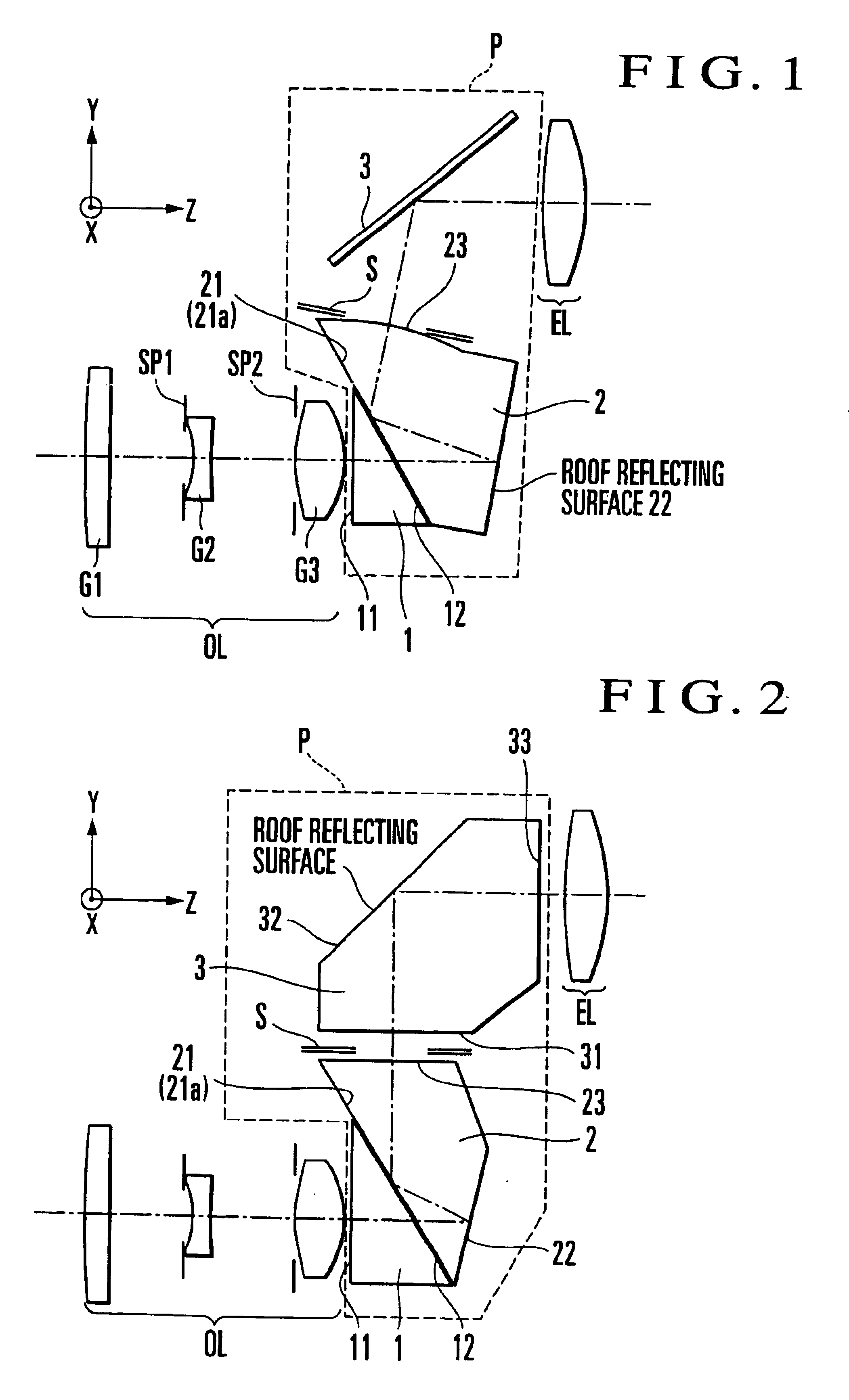
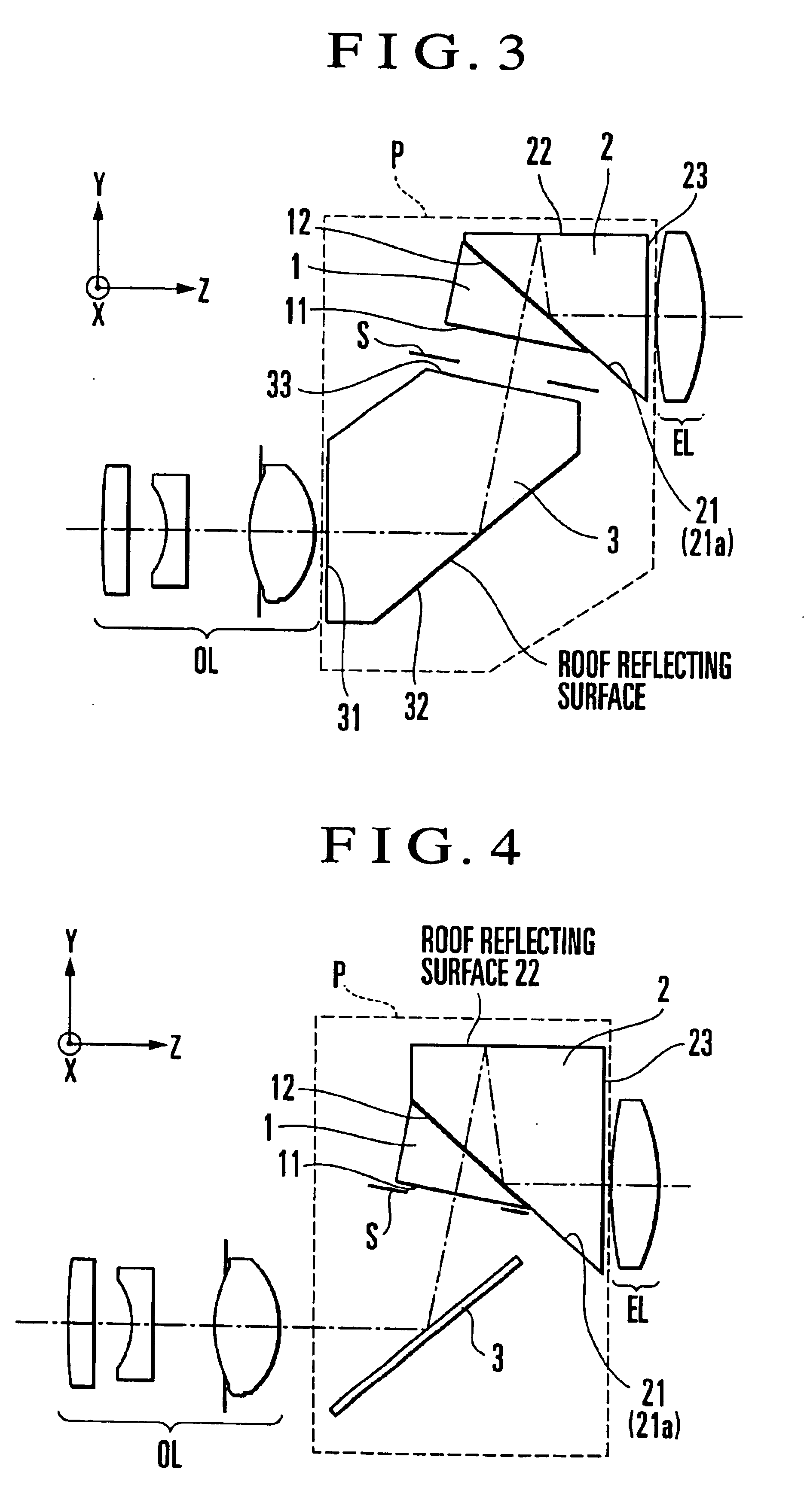
FIG. 22 is a sectional view showing essential parts of a viewfinder optical system of the real image type according to the invention. In FIG. 22, reference character OL denotes an objective lens, and reference character P denotes a prism for obtaining a non-inverted erecting image. The prism P is composed of a first prism P1 and a second prism (roof prism) P2. The first prism P1 and the second prism P2 are disposed with a minute air gap put between an exit surface 12 of the first prism P1 and an entrance surface 21 of the second prism P2. Reference character S denotes a field frame for limiting a viewfinder field. The field frame S is preferably disposed in the vicinity of an exit surface 23 of the second prism P2 (on a primary image forming plane), and may be a mechanical part or may be formed by using a light-transmission limiting pattern forming means, such as a liquid crystal element. The second prism P2 is shaped such that a light flux reflected from a roof surface 22 is made i...
tenth embodiment
Further, in a viewfinder optical system of the real image type shown in FIG. 24, which is the invention, the image inversion is performed in the first prism P41. A light flux coming from the objective lens OL is made to enter the first prism P41 and is then totally reflected by an exit surface 411 of the first prism P41 to be led downward to a roof reflecting surface 412. A light flux reflected upward by the roof reflecting surface 412 is made to exit from the exit surface 411 of the first prism P41 and then passes through an entrance surface 421 of the second prism P42. The exit surface 411 of the first prism P41 and the entrance surface 421 of the second prism P42 are disposed in such a way as to form a wedge-shaped minute air gap therebetween which becomes narrower toward the apical angle of the second prism P42. The light flux passing through the entrance surface 421 of the second prism P42 is imaged to form a viewfinder image on a primary image forming plane in the vicinity of ...
PUM
 Abstract
Description
Claims
Application Information
 - R&D
- Intellectual Property
- Life Sciences
- Materials
- Tech Scout
- Unparalleled Data Quality
- Higher Quality Content
- 60% Fewer Hallucinations
Browse by: Latest US Patents, China's latest patents, Technical Efficacy Thesaurus, Application Domain, Technology Topic, Popular Technical Reports.
© 2025 PatSnap. All rights reserved.Legal|Privacy policy|Modern Slavery Act Transparency Statement|Sitemap|About US| Contact US: help@patsnap.com


