Drive wheel bearing assembly

a technology of bearings and bearings, applied in mechanical devices, couplings, transportation and packaging, etc., can solve the problems of reducing the efficiency of replacement, difficult to completely eliminate the possibility of damage, and remaining susceptible to improvemen

Inactive Publication Date: 2004-08-24
NTN CORP
View PDF11 Cites 37 Cited by
  • Summary
  • Abstract
  • Description
  • Claims
  • Application Information

AI Technical Summary

Problems solved by technology

However, it is still difficult to totally eliminate the possibility of damage even with the boots of this type, thus remaining the boots susceptible to improvement.
This causes a decrease in efficiency of the replacement.
However, the assembly disclosed in Japanese Patent Laid-Open Publication No.Hei 10-325420 presented the following problems.
This caused the centrifugal force due to rotation to increase, thereby leading to an increase in expansion of the boot and leaving in particular a durability problem at high speeds.
In addition, a spacer added to the intermediate shaft causes an increase in the weight of the intermediate shaft, thus causing an increase in consumption of fuel and making it difficult to reduce the weight of the assembly.
In addition, an increase in the space of the outer diameter portion may cause a problem of interfering with the surrounding parts to occur.
This shows that the serrations fit too tightly to each other to prevent circumferential play would make it difficult to assure the engagement of the keeper ring 20 in place (in the annular grooves), and thus the serrations have to be loosely engaged with each others.
Accordingly, the extended portion 16 provided on the edge portion of the hub ring 7 causes not only an increase in weight of the entire assembly but also some degradation in steering performance due to a displacement of the joint center in an axially inboard direction.
However, the aforementioned structure allows the joint center to be displaced in an axially inboard direction and thus causes some degradation in running stability.
However, such robust fastener means would cause the structure to become more complicated or an increase in number of the parts, and thus would not be preferably provided.
However, the re-setting or caulking would possibly cause a lack or an excess of preload which may have an adverse effect on the rigidity and life of the bearing, therefore leaving a good deal desired to be solved.
This provides a large number of combinations between the bearing assembly and the constant velocity universal joint, thus making the aforementioned caulking complicated in the manufacturing steps.

Method used


Image

  • Drive wheel bearing assembly
  • Drive wheel bearing assembly
  • Drive wheel bearing assembly

Examples


Embodiment Construction

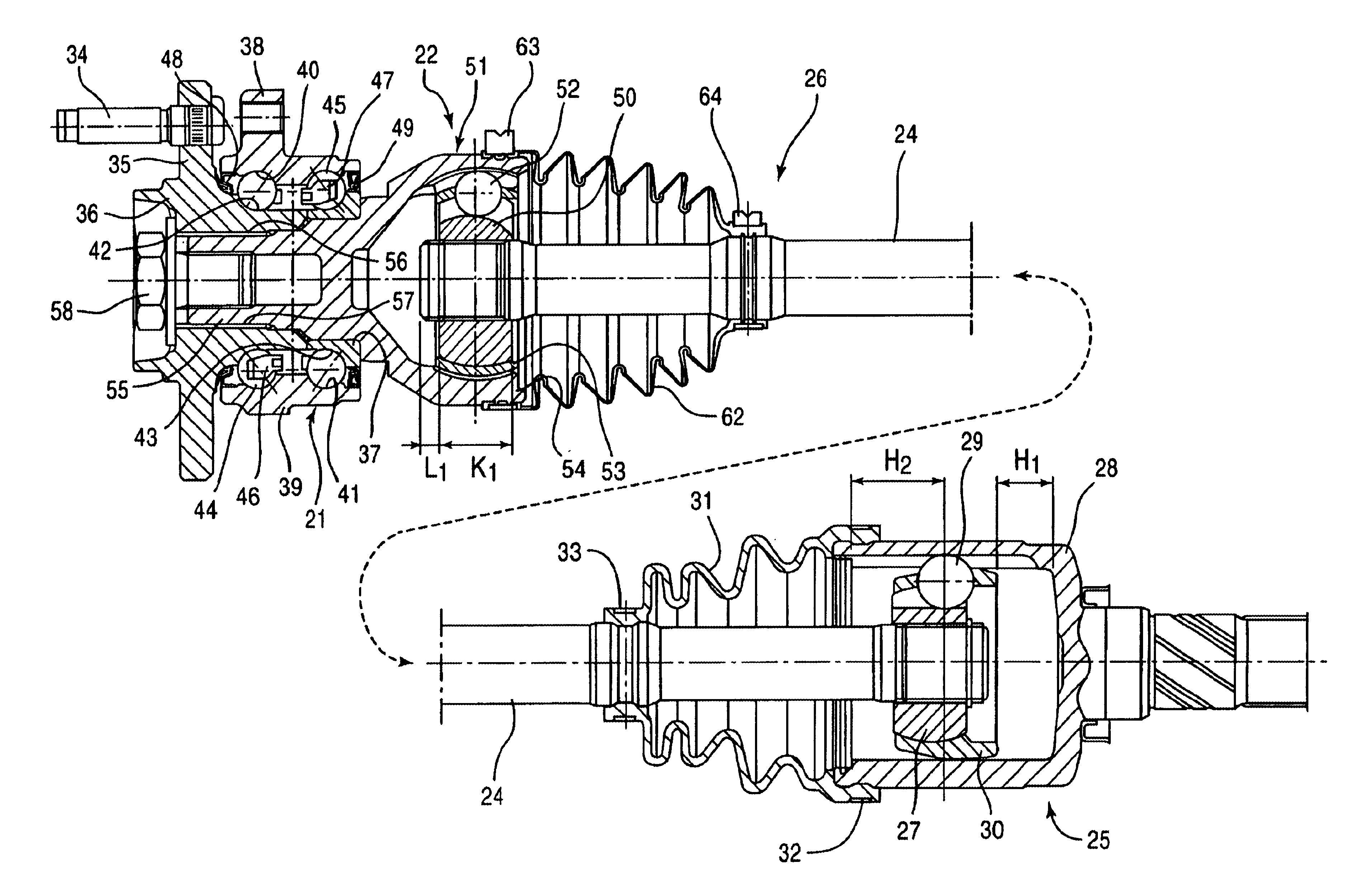
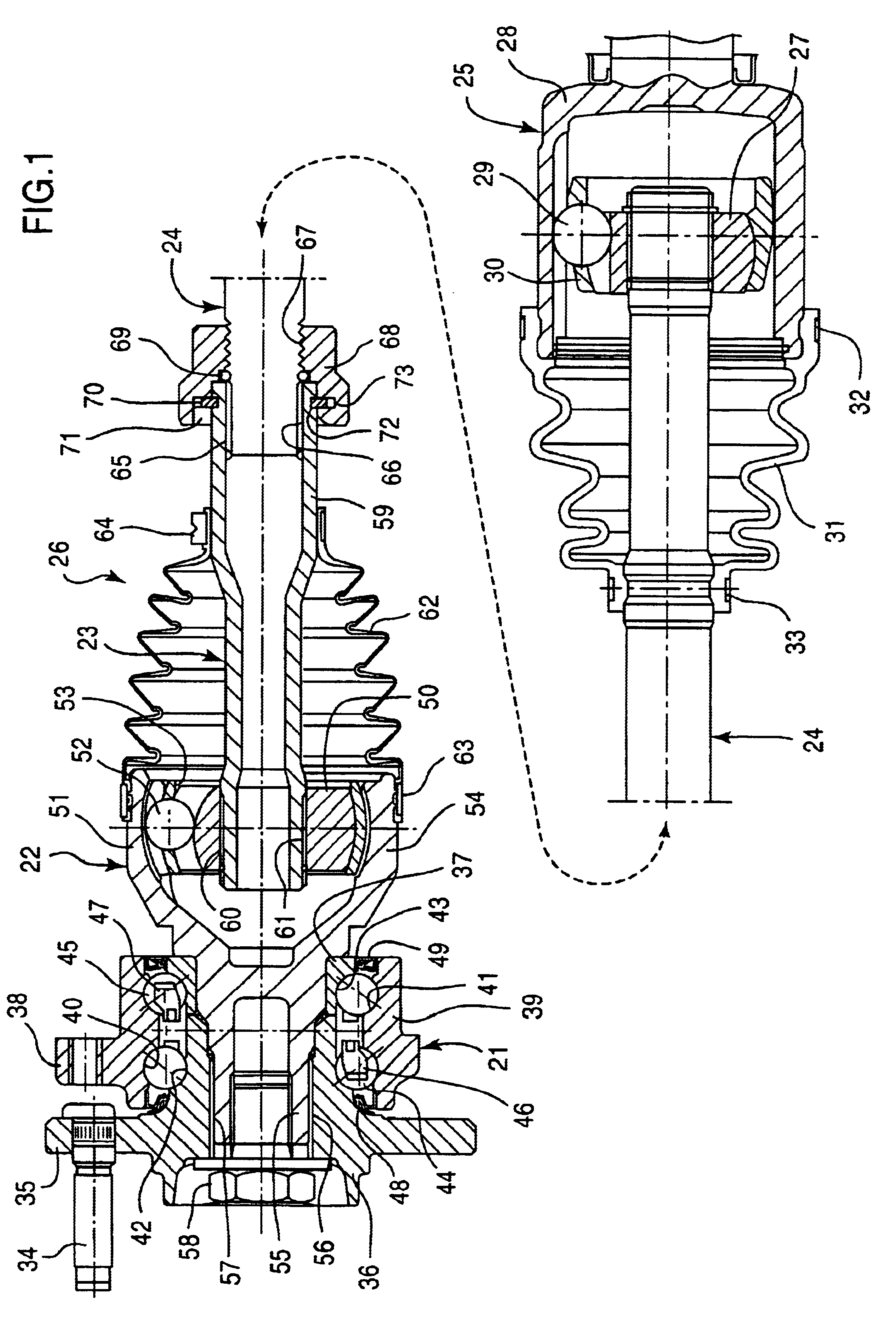
An embodiment shown in FIG. 1 has a structure in which a wheel bearing 21 is integrally unitized with a fixed type constant velocity universal joint, and the fixed type constant velocity universal joint 22 is mounted to one end of an intermediate shaft 24 via a stub shaft 23, while a sliding type constant velocity universal joint 25 connected to a differential is mounted to the other end of the intermediate shaft 24. The fixed type constant velocity universal joint 22 and the wheel bearing 21 are unitized to form a bearing assembly in which the fixed type constant velocity universal joint 22, the sliding type constant velocity universal joint 25, and the intermediate shaft 24 to be connected therebetween constitute a drive shaft 26.

With the drive shaft 26 being mounted to the vehicle body, the constant velocity universal joints 22, 25 are provided with a specified operative angle. The operative angle of the constant velocity universal joints 22, 25 changes when an empty vehicle is f...


PUM


Abstract

In a drive wheel bearing assembly, a fixed type constant velocity universal joint is coupled to a wheel bearing, mounted to one end of an intermediate shaft, and a sliding type constant velocity universal joint, is coupled to a differential, mounted to the other end portion of the intermediate shaft. One end portion of a stub shaft is connected to an inner joint ring of the constant velocity universal joint via torque transmission portions; one end portion of the intermediate shaft is connected to the other end portion of the stub shaft via torque transmission portions. A threaded portion is formed on an outer diameter portion of either the intermediate or stub shaft; a nut member threadedly engages the threaded portion; and a keeper ring is fitted into annular grooves formed on the outer diameter portion of the intermediate shaft or the stub shaft and an inner diameter portion of the nut member allowing the nut member to rotate, but not move axially.

Description

1. Field of the InventionThe present invention relates to drive wheel bearing assemblies and, more particularly, to a drive wheel bearing assembly comprising drive shafts and wheel bearings for use in power transmission systems for transmitting power from the engine of vehicles to the drive wheels.2. Description of the Background ArtThe power transmission system for transmitting power from the engine of a vehicle to the drive wheels needs to respond to angular and axial displacements caused by a change in the relative positional relationship between the engine and the wheels. For example, as shown in FIG. 40, there is interposed an intermediate shaft 1 between the engine and the drive wheel, and one end of the intermediate shaft 1 is coupled to a differential via a sliding type constant velocity universal joint J.sub.1, while the other end thereof is coupled to a wheel rib 2 via a fixed type constant velocity universal joint J.sub.2 and a wheel bearing 8. There are installed seal bo...

Claims


Application Information

Patent Timeline
Patent Type & Authority Patents(United States)
IPC IPC(8): B60B27/00
CPCB60B27/00Y02T10/86Y10S464/906F16D1/116F16D2001/103F16D2003/22313F16D2003/22323
Inventor SAHASHI, KOJIHOZUMI, KAZUHIKOSONE, KEISUKEOZAWA, MASAHIROTORII, AKIRAOGURA, HIROYUKIUMEKIDA, MITSURUFUKUSHIMA, SHIGEAKITAJIMA, EIJIOHTSUKI, HISASHI
Owner NTN CORP
Why Eureka
Try Eureka