
Mechanism and system for 3-dimensional scanning of an ultrasound beam

a technology of ultrasound beam and system, applied in tomography, applications, instruments, etc., can solve the problems of increasing the impedance of elements and hence noise, reducing the size of elements, increasing the loss of cables and hence array sensitivity,

Inactive Publication Date: 2004-08-24
PREXION
View PDF17 Cites 35 Cited by
  • Summary
  • Abstract
  • Description
  • Claims
  • Application Information

AI Technical Summary

Benefits of technology

Enables high-sensitivity, high-resolution 3D ultrasound imaging with a small, easy-to-handle probe suitable for endoluminal and surgical applications, reducing noise and cable losses while maintaining high-frequency capabilities.

Problems solved by technology

A problem with the subdivision of the elements is that the size of the elements are reduced, increasing the element impedance and hence also noise.
This increases cable losses and hence sensitivity of the array.
A problem with the annular array for 3D beam scanning, is that scanning of the beam direction requires mechanical movement of the array.

Method used


Image

  • Mechanism and system for 3-dimensional scanning of an ultrasound beam
  • Mechanism and system for 3-dimensional scanning of an ultrasound beam
  • Mechanism and system for 3-dimensional scanning of an ultrasound beam

Examples


Embodiment Construction

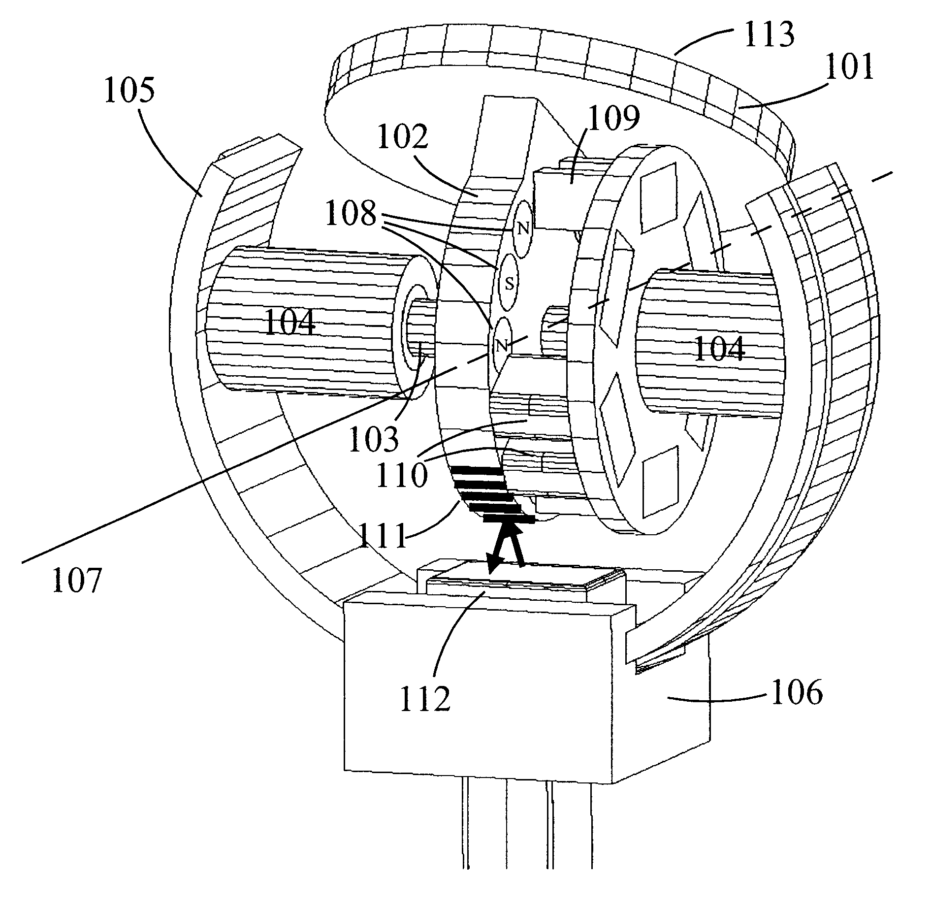
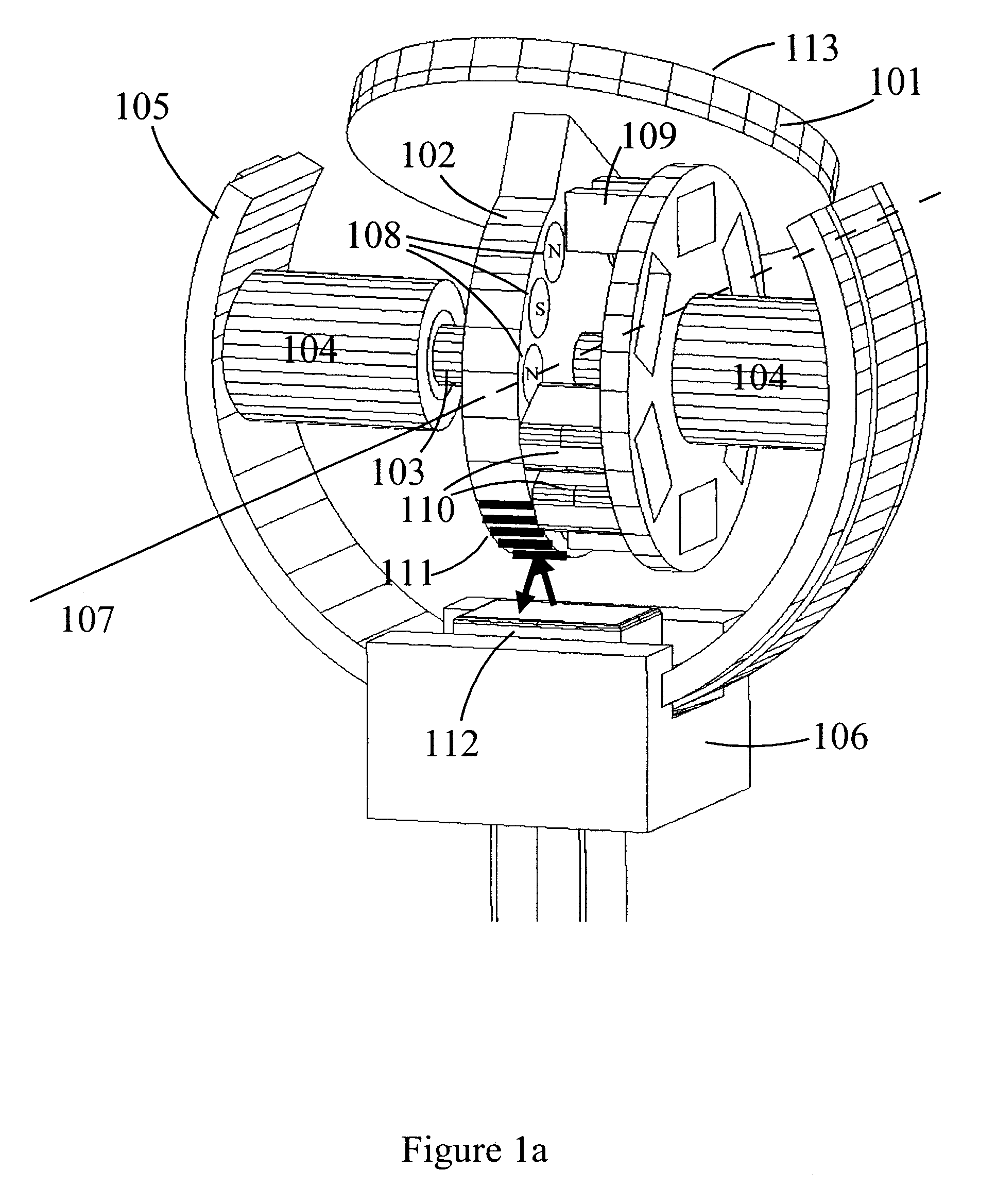
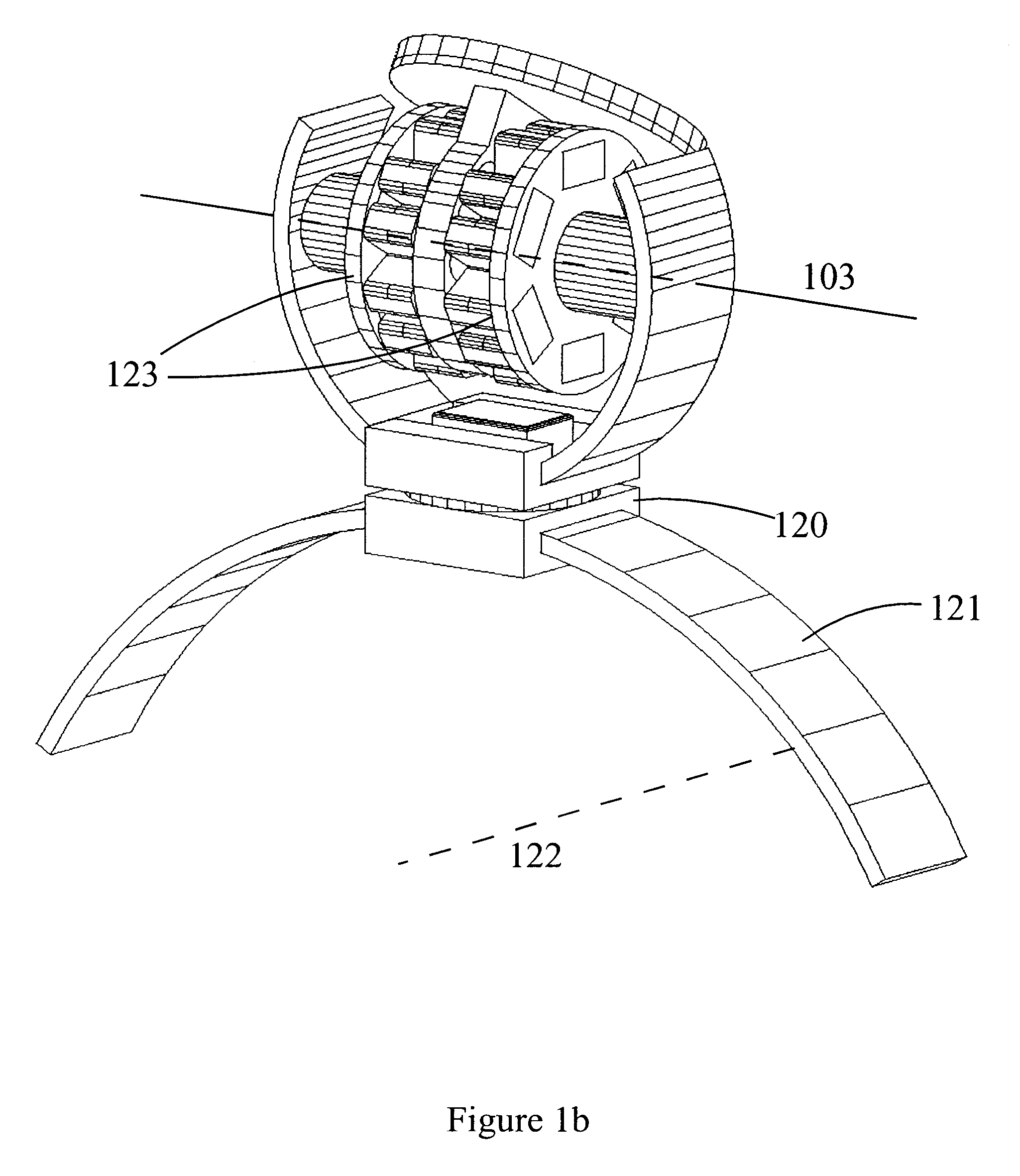
A particular embodiment of the invention will be described with reference to the drawings. In FIG. 1a 101 shows an annular array that is attached to the rotor 102 of an electric motor that is attached to a shaft 103 that is free to move in bearings 104 mounted in a fork 105. Rotating the array around the shaft 103 scans the ultrasound beam in an angular direction referred to as the azimuth direction, within a 2D plane referred to as the azimuth plane. The fork 105 is mounted in a sliding system 106 which allows movement of the shaft. In this particular embodiment, the fork has a circular shape so that sliding of the fork through the sliding system produces a rotation of the shaft 103 around an axis 107, normal to the shaft, which allows angular scanning of the beam in what is referred to as the elevation direction. Moreover, this particular embodiment produces a rotation of the shaft around an axis on the same side of the sliding system as the shaft itself, and the axis 107 goes thr...


PUM


Abstract

An ultrasound probe capable of scanning an ultrasound beam in a region of 3D space, characterized by that an ultrasound transducer array is mounted to a 1<st >shaft that can rotate in bearings mounted in a fork that can be moved. The fork can be rotated around a 2<nd >shaft in a bearing, or moved through a sliding system, or a combination of the two. The shaft and the fork are connected to two separate electric motors for electric steering of the array direction within a region of 3D space. Position measurement systems are mounted to the shaft and the fork so that the beam direction can be steered with a feed-back control system.

Description

1. Field of the InventionThe present invention is directed to technology and methods for scanning an ultrasound beam in a free direction within a region of 3D space. The technology has particular applications within 3D medical ultrasound imaging, but also has applications in other areas of ultrasound imaging or other areas where mechanical movement of an object in 3D space is required.2. Description of the Related ArtThree-dimensional (3D) ultrasound imaging of biological structures can be done by scanning a pulsed ultrasound beam in a 3D manner, and recording the back-scattered ultrasound signal in each beam direction. The principle was described already in the 50'ies, and several instruments have been built that applies the method.With 3D imaging, it is important that the ultrasound beam is maximally focused, symmetrically in all directions around the beam axis, as one wants to observe the object from any direction (perspective), and small objects can be interrogated with a variet...

Claims


Application Information

Patent Timeline
Patent Type & Authority Patents(United States)
IPC IPC(8): A61B8/00
CPCA61B8/00A61B8/4461A61B8/483G01S15/8936G01S15/8993
Inventor ANGELSEN, BJ.O SLASHED.RN A. J.JOHANSEN, TONNI F.KJ.O SLASHED.DE, STIG B.
Owner PREXION
Learn More