Cross-flow filter membrane and method of manufacturing it

a filter membrane and cross-flow technology, applied in gravity filters, loose filtering materials, stationary filtering elements, etc., can solve the problems of head loss, different separation conditions along the channel, and non-uniform separation

Inactive Publication Date: 2004-08-24
TECH AVANCEES & MEMBRANES INDS
View PDF6 Cites 67 Cited by
  • Summary
  • Abstract
  • Description
  • Claims
  • Application Information

AI Technical Summary

Problems solved by technology

Fluid friction thus arises on the surfaces of the channels and causes head loss which varies linearly as a function of channel length.
This permeate flow rate gradient leads to non-uniformity in the separation performed by the membrane and leads to different separation conditions appearing along the channels.
Such a device presents the drawback of requiring a permeate recirculation loop to be implemented, thereby considerably complicating manufacture of such devices and increasing the energy cost associated with operating the additional loop.
Although such a solution makes it possible to modify the support only, that technique suffers from the drawback of reducing the external porosity of the support and thus facilitates the accumulation of molecules or particles which have passed through the separator layer and which statistically can be stopped by the portion of the support having reduced porosity.
In practice, the diameter of the pores on a transverse right-section of such a support increases and then diminishes at its periphery, so a risk appears of molecules or particles accumulating.
Such accumulation can lead to the support being destroyed.
Under such conditions, the porosity gradient implemented in this way leads to a permeate flow arising that is non-uniform along the length of the membrane.

Method used


Image

  • Cross-flow filter membrane and method of manufacturing it
  • Cross-flow filter membrane and method of manufacturing it
  • Cross-flow filter membrane and method of manufacturing it

Examples


Embodiment Construction

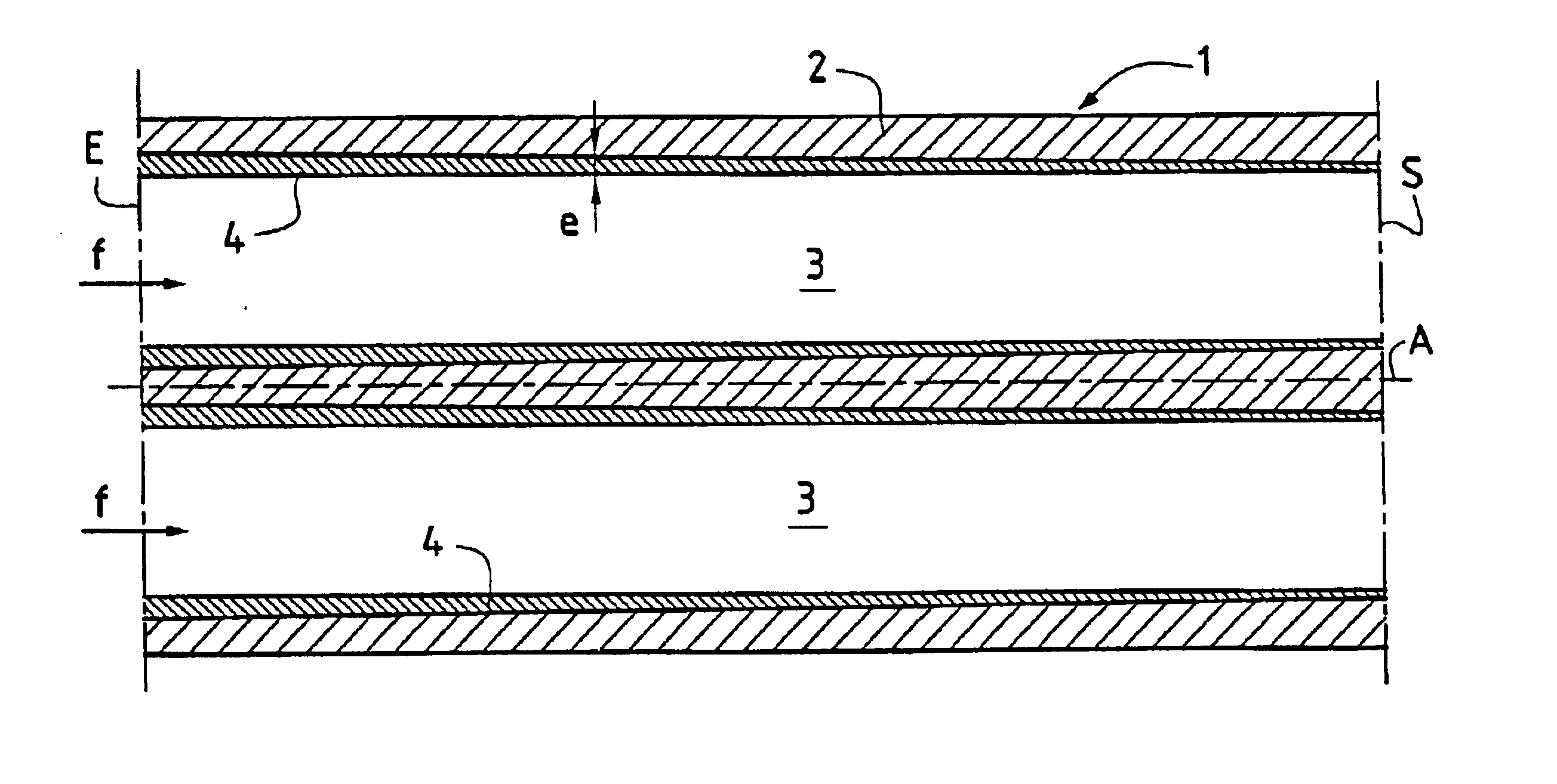
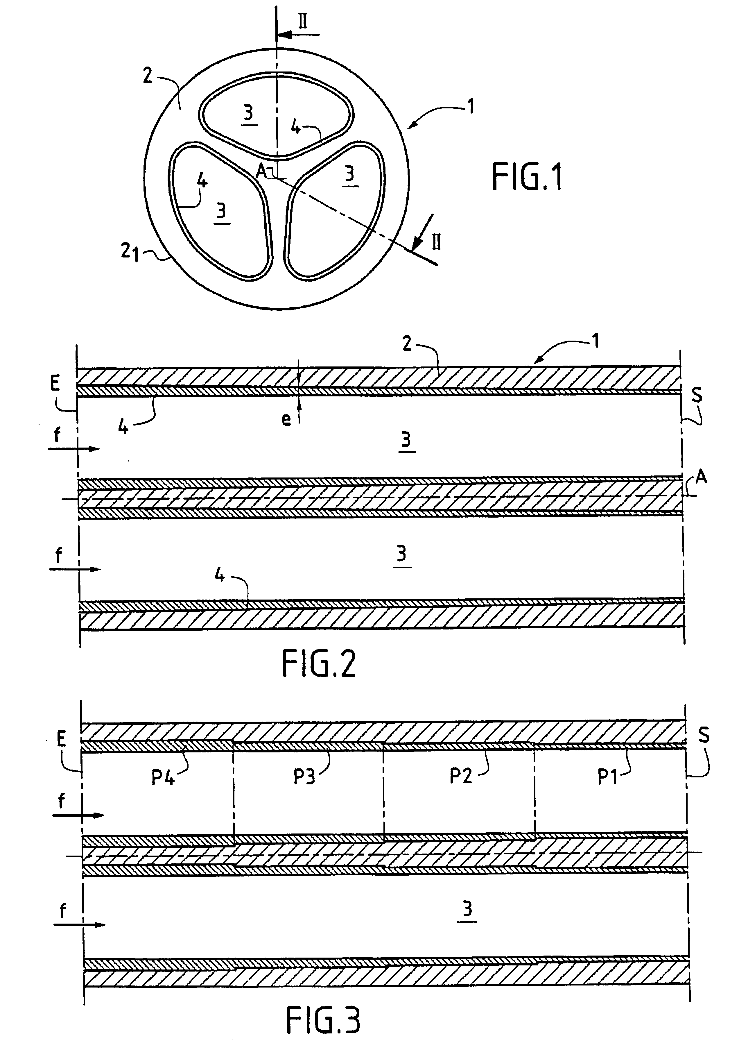
As can be seen from FIGS. 1 and 2, the filter membrane 1 of the invention is adapted to separate or filter out molecules or particles contained in various kinds of fluid medium, preferably liquids, and optionally containing a solid phase. In the embodiment shown, the filter membrane 1 is of the tubular type. In this example, the filter membrane 1 has an inorganic rigid porous support 2 made of a material whose transfer resistance is adapted to the separation that is to be performed. The porous support 2 is made of inorganic material, such as a metal oxide, carbon, or metal. In this embodiment, the porous support 2 is elongate in shape, extending along a central longitudinal axis A. The porous support 2 has a polygonal right cross-section or, as shown in FIGS. 1 and 2, a circular cross-section. The porous support 2 thus presents an outside surface 2.sub.1 that is circularly cylindrical.

The porous support 2 is arranged to have at least one channel, and in the example shown it has thre...


PUM

PropertyMeasurementUnit
lengthaaaaaaaaaa
diameteraaaaaaaaaa
diameteraaaaaaaaaa

Abstract

The invention provides a membrane for cross-flow filtering of a fluid to be treated, said membrane comprising an inorganic rigid porous support defining at least one flow channel for the fluid to be treated flowing in a given direction, the surface of the channel being covered in at least one separator layer separating out from the fluid to be treated a fraction referred to as the permeate which passes through the layer and the support. According to the invention, the separator layer presents a thickness gradient that decreases in the flow direction of the fluid to be treated.

Description

The present invention relates to the technical field of separating out molecules or particles by implementing separator elements generally known as "membranes" and made out of inorganic materials and constituted by a rigid porous support having at least one flow channel for a fluid medium, with at least one separator layer being deposited on the surface thereof, the nature and the morphology of the layer being adapted to separate out molecules or particles contained in the fluid medium for treatment.More precisely, the invention relates to making separator layers forming parts of inorganic membranes.A particularly advantageous application of the invention lies in the fields of nanofiltration, ultrafiltration, microfiltration, filtration, and reverse osmosis.In conventional manner, a membrane is defined by associating a porous support made of inorganic material, such as a ceramic, with one or more separator layers of inorganic material deposited on the surface of each flow channel an...

Claims


Application Information

Patent Timeline
Patent Type & Authority Patents(United States)
IPC IPC(8): B01D63/06B01D61/08B01D69/12B01D61/18B01D69/04B01D69/10B01D71/02
CPCB01D63/061B01D63/066B01D2313/08B01D2315/10
Inventor GRANGEON, ANDRELESCOCHE, PHILIPPEFLEISCHMANN, THOMASRUSCHEL, BERND
Owner TECH AVANCEES & MEMBRANES INDS
Why Eureka
Try Eureka