Method and device for controlling units in a vehicle according to the level of noise

Inactive Publication Date: 2004-08-31
ROBERT BOSCH GMBH
View PDF13 Cites 14 Cited by
  • Summary
  • Abstract
  • Description
  • Claims
  • Application Information

AI Technical Summary

Problems solved by technology

These aggregates emit noises which, in certain operating situations, are perceived as being disturbing and a nuisance by the passengers in the vehicle.
Here too, a very costly method is used to keep the generator's noise emission low.
It has been shown that the cited related art is not able to obtain optimal results in every respect.
Thus, in spite of costly control methods, a loss of

Method used


Image

  • Method and device for controlling units in a vehicle according to the level of noise
  • Method and device for controlling units in a vehicle according to the level of noise
  • Method and device for controlling units in a vehicle according to the level of noise

Examples


Embodiment Construction

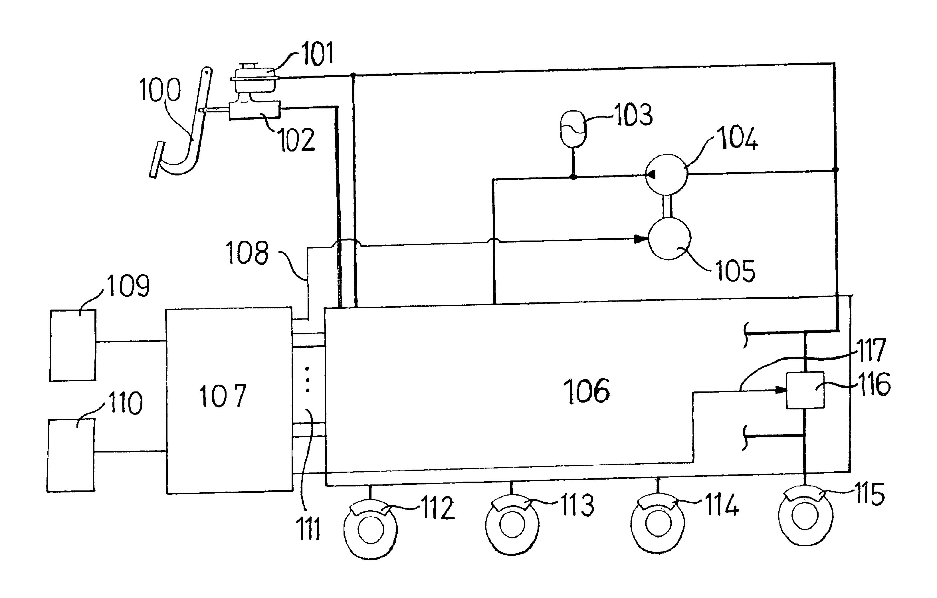
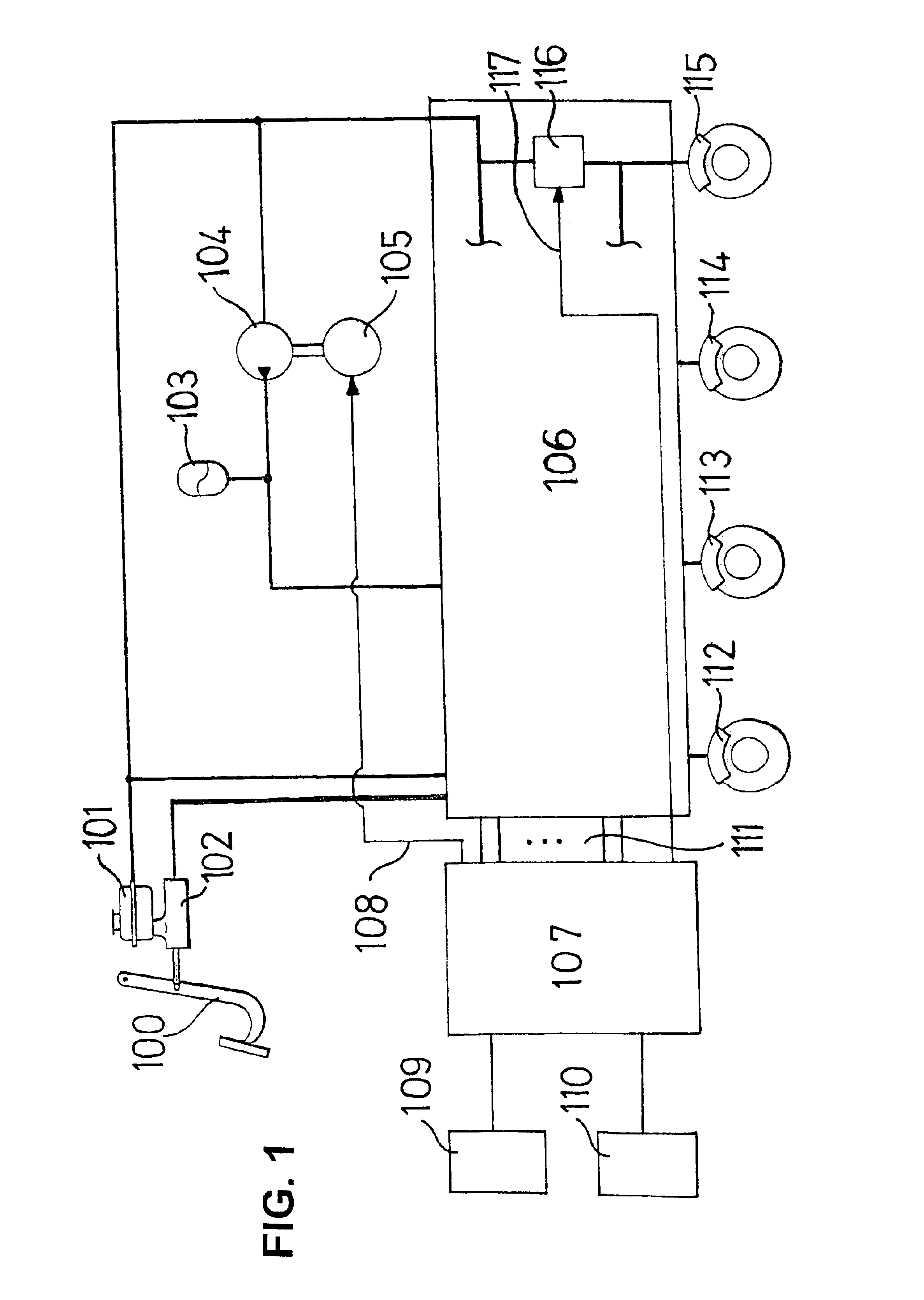
FIG. 1 shows a braking system, especially an electrohydraulic braking system, in which the brake fluid is applied from an hydraulic accumulator 103 via valves 116 into wheel braking cylinders 112 through 115. The hydraulic accumulator is charged using a means for propelling the pressure mediun, in the form of a pump 104. If possible, this charging should take place without perceptible noise development.

In the braking system shown, a brake pedal 100 is illustrated which is connected to a master brake cylinder 102. By the application of the brake pedal, pressure can be built up in master brake cylinder 102. Master brake cylinder 102 is in contact with a reservoir 101. From master brake cylinder 102 as well as reservoir 101 lines for the pressure medium lead to braking system 106. Braking system 106 includes valve means and possible pressure sensing, as well as, in the case of an electrohydraulic braking system, a possible pedal travel simulator and other components known from the rela...


PUM


Abstract

A method, a device, and a control unit are for controlling at least one aggregate in a vehicle, the noise caused by the aggregate and/or at least one variable representing this noise being ascertained. The passenger compartment noises in the vehicle are ascertained, or at least one variable representing these is ascertained. The noise caused by the aggregate and/or the variable representing this is correlated with the passenger compartment noises and/or the variable representing these. As a function of that, the control or a control signal for the aggregate is generated and/or adapted.

Description

BACKGROUND INFORMATIONThe present invention relates to a method and device for controlling aggregates in a vehicle according to the definition of the species in the independent claims.The number of aggregates built into vehicles is growing steadily. These aggregates emit noises which, in certain operating situations, are perceived as being disturbing and a nuisance by the passengers in the vehicle. In order to tone down these disturbing and irritating noises, the aggregates are controlled by complex methods for the purpose of reducing the noise.To do this, in DE 195 48 248 A1 a method and a device for controlling the pump of an electrohydraulic braking system is proposed. In this instance, hydraulic fluid from a pressure accumulator is applied through valves into the wheel brake cylinder, the pressure accumulator being loaded using a pump. The pump is controlled in a performance-regulated manner in such a way that charging the pressure accumulator by the pump is accomplished with as...

Claims


Application Information

Patent Timeline
IPC IPC(8): B60R16/02B60T17/02B60R16/023
CPCB60R16/0231
Inventor GRABSCH, HANS-PETER
Owner ROBERT BOSCH GMBH
Why Eureka
Try Eureka