
Method for preparing a dialkyl carbonate, and its use in the preparation of diaryl carbonates and polycarbonates

a dialkyl carbonate and polycarbonate technology, applied in the field of dialkyl carbonate preparation, can solve the problems of high cost of corrosion-resistant equipment and failure to prevent corrosion in downstream separation and purification sections, and achieve the effect of efficient utilization of residence tim

Inactive Publication Date: 2004-08-31
SABIC GLOBAL TECH BV
View PDF17 Cites 22 Cited by
  • Summary
  • Abstract
  • Description
  • Claims
  • Application Information

AI Technical Summary

Benefits of technology

In yet another embodiment, illustrated in FIG. 5, the fluid passageway 110 may comprise a section having L / V of at least 5, preferably at least about 10. For brevity, this section may be referred to as a tubular section 130. Such a tubular section 130 having L / V>5 may promote plug flow of the mixture through the fluid passageway 110, thereby efficiently utilizing the residence time for removal of the alkyl chloroformate. In this embodiment, it may be preferred that the mixture reside in one or more narrow sections having L / V>5 for at least about 50% of the total residence time spent in the fluid passageway 110, more preferably at least about 80% of the total residence time spent in the fluid passageway 110.

Problems solved by technology

Hydrochloric acid and copper chlorides are very corrosive in the presence of water, so equipment made from corrosion-resistant materials, such as glass-lined vessels, must be used in the reaction section of a chemical plant making dialkyl carbonates by this process.
As corrosion-resistant equipment is expensive, there is a desire to use it in as little of the plant as possible.
However, a technique similar to that described by the '943 Patent--removing HCl and copper salts by treatment of a vaporized feed in a column using a counterflowing azeotrope fluid from the reaction mixture--failed to prevent corrosion in the downstream separation and purification sections.

Method used


Image

  • Method for preparing a dialkyl carbonate, and its use in the preparation of diaryl carbonates and polycarbonates
  • Method for preparing a dialkyl carbonate, and its use in the preparation of diaryl carbonates and polycarbonates
  • Method for preparing a dialkyl carbonate, and its use in the preparation of diaryl carbonates and polycarbonates

Examples


examples 2-5

The decomposition kinetics of methyl chloroformate were studied under four different conditions. A procedure for determining methyl chloroformate in a sample was as follows. For Example 2, 32 milliliters (mL) of dimethyl carbonate, 10 mL of dimethyl carbonate containing 50 mg of a biphenyl internal standard 63 mL of methanol, and 5 ml of water were added to a 250 mL flask equipped with a thermometer, a condenser, and a port for sampling. (Toluene may be used instead of the methanol / water solution.) The resultant homogeneous solution was placed in an oil bath and the temperature of the solution was held constant at 50.degree. C. At time zero, 81.7 microliters of pure methyl chloroformate were added to the solution (1,000 ppm on a weight basis). Samples were withdrawn at various time intervals and were quenched by reacting the methyl chloroformate in the sample with diisobutyl amine to convert the methyl chloroformate to N,N'-diisobutyl methyl carbamate. The amount of N,N'-diisobutyl ...

example 6

Comparative Example 1

These experiments show that the fluid passageway 110 is effective to reduce the concentration of methyl chloroformate that can react to form HCl in downstream sections of the plant. With reference to FIG. 1, two samples were obtained by sampling the process fluid at different points in a dimethyl carbonate plant having a configuration with a first heat exchanger 140 and two holding vessels 120 (i.e., a configuration corresponding to FIG. 3). The first sample (Comparative Example 1) was taken immediately before the first heat exchanger 140. The second sample (Example 6) was taken after the second holding vessel 120 (i.e., after the fluid passageway 110). Each same was taken to the lab, and its chloride content was determined as a function of time elapsed from sampling. The results are presented in Table II. The Ex. 6, data show essentially constant levels of chloride ion, indicating that labile, chloride-generating species such as methyl chloroformate are not pre...

example 7

Comparative Example 2

For Comparative Example 2, a dimethyl carbonate plant according to simplified FIG. 2 was operated according to the conditions described in Table III, below. This plant was similar to that shown in more detail in FIG. 1, with the exception that the first heat exchanger 140 and the fluid passageway 110 were absent. Corrosion was observed in and downstream of the azeotrope column 180. Next, this plant was modified to include the first heat exchanger 140 and two holding vessels 120 were added to increase residence time (i.e., FIG. 3 configuration). FIG. 10 presents measurements of residual ionic chlorides found in samples taken from the bottom of the azeotrope column 180, comparing the FIG. 2 and FIG. 3 configurations, each over time. Residual chlorides were determined by titration using a silver nitrate solution, as described above. The data for the FIG. 2 configuration have an average of 671 ppm chloride with a standard deviation of 370 ppm chloride, whereas the d...


PUM

PropertyMeasurementUnit
molar ratioaaaaaaaaaa

Abstract

Unexpected corrosion of downstream sections of a dialkyl carbonate manufacturing apparatus has been traced to alkyl chloroformate impurities, which slowly decompose to yield hydrochloric acid. An improved process and apparatus for dialkyl carbonate synthesis reduce corrosion by physically removing or chemically decomposing the alkyl chloroformate impurities within the corrosion-resistant upstream sections of the apparatus.

Description

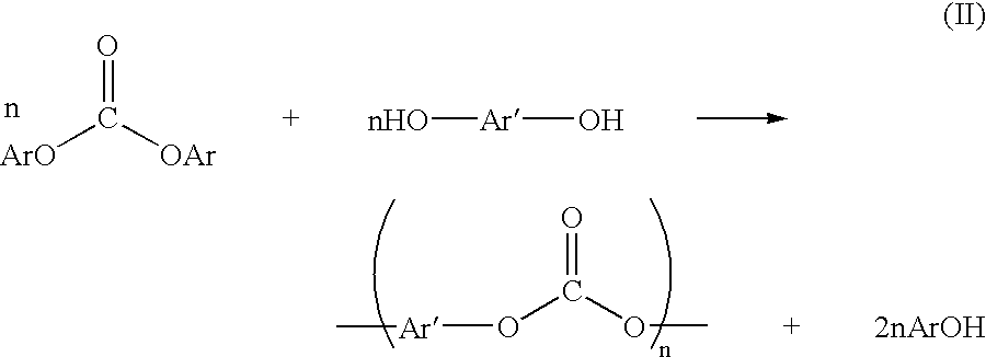
BACKGROUND OF INVENTIONPolycarbonate resins are useful materials valued for their physical and optical properties. Methods for the preparation of polycarbonate resins include interfacial processes and melt processes. In interfacial processes, as described, for example, in U.S. Pat. No. 4,360,659 to Sikdar, a bisphenol is reacted with phosgene in the presence of solvents. In melt processes, as described, for example, in U.S. Pat. No. 3,153,008 to Fox, a bisphenol is reacted with a diaryl carbonate. Melt processes are presently preferred because they avoid the use of phosgene and solvents.Use of a melt process for polycarbonate synthesis requires an industrially efficient process for producing diaryl carbonates. There are several known processes for producing diaryl carbonates. One example of such a process is described by U.S. Pat. No. 4,182,726 to Illuminati et al. In this process, diaryl carbonates are produced by reacting dialkyl carbonates with aryl hydroxides (see Scheme I, belo...

Claims


Application Information

Patent Timeline
Patent Type & Authority Patents(United States)
IPC IPC(8): B01J19/00C07C68/00
CPCB01J19/002C07C68/005C07C69/96B01J2219/00006B01J2219/00247B01J2219/00272C07C68/01
Inventor BODEN, EUGENE PAULINGFERNANDEZ, IGNACIO VIC
Owner SABIC GLOBAL TECH BV
Learn More