Material analysis

a material analysis and material technology, applied in the field of material analysis, can solve the problems of standing waves being set up, generating hot spots, and misidentification of damage within the sampl

Inactive Publication Date: 2004-09-07
AIRBUS OPERATIONS LTD
View PDF15 Cites 24 Cited by
  • Summary
  • Abstract
  • Description
  • Claims
  • Application Information

AI Technical Summary

Problems solved by technology

However, this approach results in standing waves being set up in the sample under inspection and generating hot spots.
These hot spots are indistinguishable from damaged areas and so often result in misidentification of damage within the sample.
This approach also has the disadvantage that readings can only be obtained for the overall probed area and does not allow finer analysis of sub-regions within the area.
Whilst these prior art techniques can be useful for several types of material analysis, they are limited in usefulness for detecting barely visible impact damage (BVID) which exhibit areas of shattered material.

Method used


Image

  • Material analysis
  • Material analysis
  • Material analysis

Examples


Embodiment Construction

The invention may be performed in various ways, and various embodiments thereof will now be described in detail, reference being made to the accompanying drawings in which:

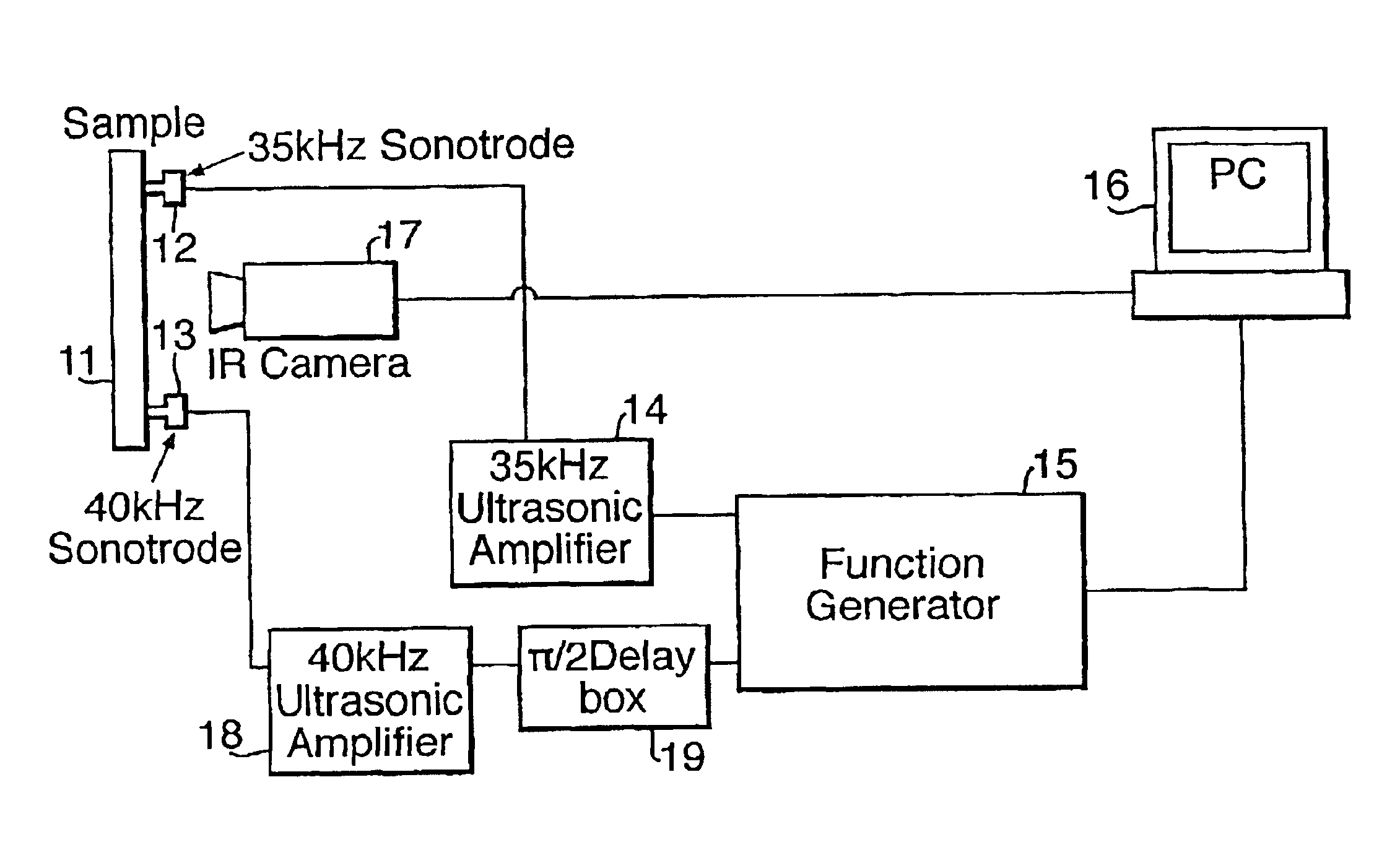
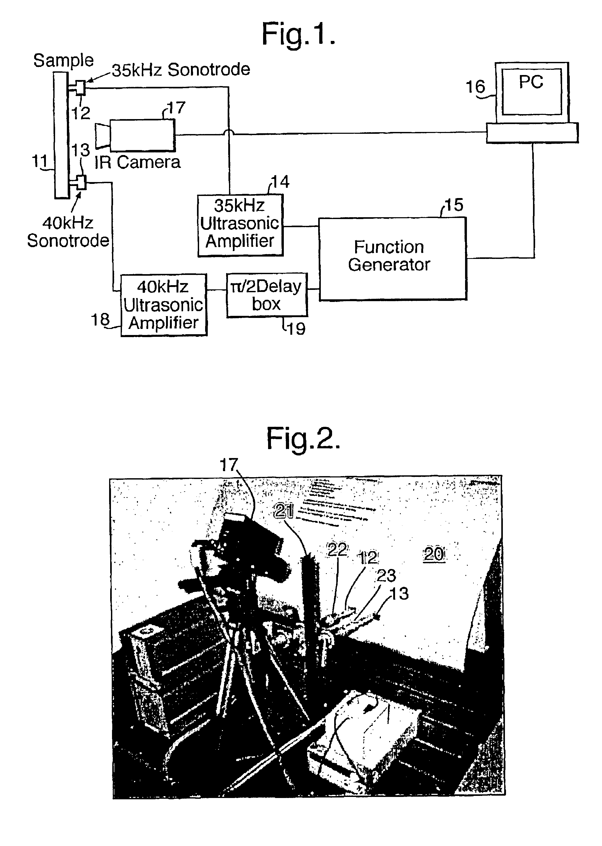
FIG. 1 is a schematic view of a preferred embodiment of the present invention;

FIG. 2 is a pictorial representation of equipment to implement the modified amplitude modulated lock-in ultrasonic TNDT technique;

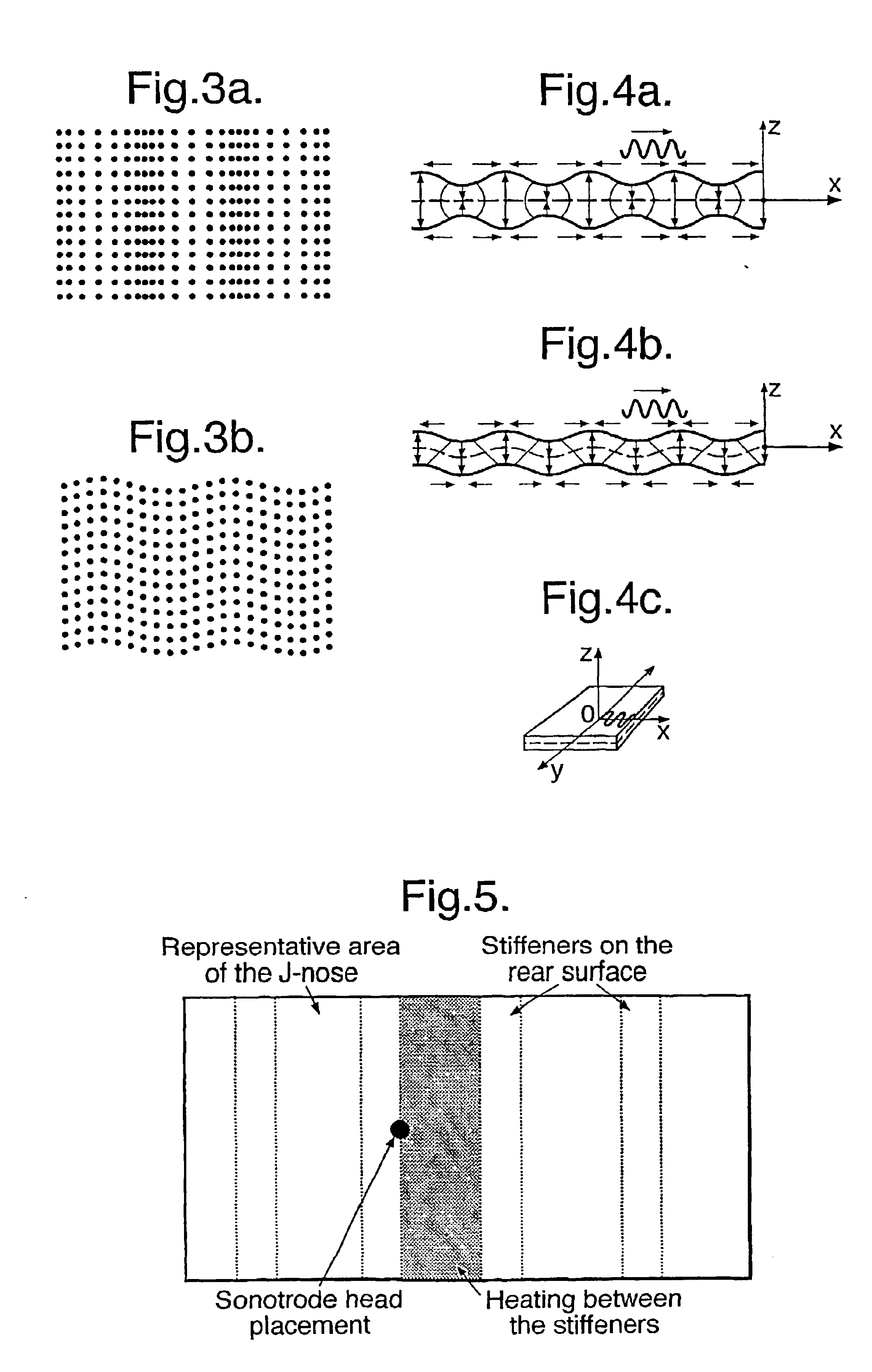
FIG. 3 shows, diagramatically, longitudinal (a) and shear (b) waves in an infinite solid;

FIG. 4 is a schematic representation of vibrational motion of (a) symmetric and (b) anti-symmetric Lamb waves and (c) transverse waves-in plates;

FIG. 5 shows placement of a sonotrode head to couple the ultrasonic energy;

FIG. 6 shows a lock-in amplitude thermal image for 0.05 Hz modulation frequency;

FIG. 7 shows a 40 kHz amplitude image for 0.15 Hz modulation frequency;

FIG. 8 shows a 35 kHz amplitude image for 0.05 Hz modulation frequency;

FIG. 9 shows an amplitude image for vertically oriented 35 kHz and 40 kHz sonotrodes u...


PUM

PropertyMeasurementUnit
frequencyaaaaaaaaaa
ultrasonic frequencyaaaaaaaaaa

Abstract

Material analysis apparatus and method, particularly of use in detecting barely visible impact damage but also of use to detect other material characteristics. The apparatus includes a function generator which provides a sinusoidal signal to an ultrasonic amplifier as well as to a PC. The PC is connected to an infrared camera. The sinusoidal signal is fed into the amplifier and causes two probes attached to the sample of material to emit ultrasonic energy at the modulated frequency. Ultrasonic energy from the two probes then enters the sample by means of mechanical coupling and an image of the resulting thermal radiation is captured by the infrared camera and transferred to the PC for further processing and analysis.

Description

1. Field of the InventionThe present invention relates to material analysis.2. Discussion of Prior ArtKnown methods of material analysis include using an intensity modulated ultrasonic source to measure material properties. In such prior art systems, a single ultrasonic probe operating at a single frequency is aimed towards a sample of a material. The resulting vibrations through the sample are measured in order to obtain data about the sample.The known ultrasonic material analysis apparatus uses only one ultrasonic transducer operating at a single frequency with an amplitude modulated by a second frequency and using intensity detectors to obtain a reading of ultrasonic absorption. However, this approach results in standing waves being set up in the sample under inspection and generating hot spots. These hot spots are indistinguishable from damaged areas and so often result in misidentification of damage within the sample. This approach also has the disadvantage that readings can on...

Claims


Application Information

Patent Timeline
Patent Type & Authority Patents(United States)
IPC IPC(8): G01N25/72G01N29/34G01N29/24G01N29/22
CPCG01N25/72G01N29/228G01N29/2418G01N29/348G01N2291/0421G01N2291/0422
Inventor BATES, DANIEL
Owner AIRBUS OPERATIONS LTD
Why Eureka
Try Eureka