Generating an inhibit signal by pattern displacement

a technology of inhibit signal and pattern displacement, which is applied in the direction of color television details, television systems, instruments, etc., can solve the problems of destroying a portion of the matte, and affecting the presentation effect of the audience,

Inactive Publication Date: 2004-09-14
IMATTE INC
View PDF5 Cites 38 Cited by
  • Summary
  • Abstract
  • Description
  • Claims
  • Application Information

AI Technical Summary

Benefits of technology

To develop a reliable binary selective inhibit signal accurately identifying those pixels comprising the presenter's silhouette; where said signal is immune to a subject's infrared reflection levels and immune to randomly occurring non-uniform infrared flooding of the projection screen and presenter.
Four key elements make a stable Inhibit Signal possible. They are: 1) the use of a projected pattern upon the screen and presenter using non-visible infrared, 2) the lateral displacement of an infrared camera whose image of the pattern will be displaced for any subject not in the plane of the screen, 3) a unique pattern, such as a random noise pattern, whose displaced image will no longer match the original image, thus making a presenter's infrared reflectance irrelevant, and 4) the comparison of differentiated pattern signals, thus providing immunity to infrared spill on the projection screen.
Comparing the differentials of the reference frame and current frame signals, rather than comparing the original signals, achieves immunity to randomly occurring infrared spill onto the projection screen, especially when the spill is a streak of light across the screen from an opened door. The difference in signal level between two adjacent pixels (a differential) is the same whether this difference occurs at low or high levels of spill light
FIG. 4 is a configuration in which computer 21 stores data images and makes all of the computations shown in dotted box 8 of FIG. 3. Housing 4 contains only the IR projector 6 projecting a pattern, and TR camera 7 providing an image of the projected pattern to processing functions 8 located within computer 21. The output of inhibit function 20 is the inhibited current image, and is routed to image projector 3. The advantage of this configuration is its simplicity and the use of a desktop computer to perform all computations.
In FIG. 6 the image inhibit function 20 has been moved from computer 21 to IR housing 4, where hard-wired circuits further reduce the delay by which the inhibit signal follows the motions of the presenter. Image storage 9 is used only for the storage of the presenter's data images. There is no inhibiting penalty in a slow transfer of a stored data image in computer 21 to inhibit function 20 in housing 4.
Configuration 6, using hard-wired circuits, provides minimum time delay between a presenter's motion and the motion of the mask that covers him.

Problems solved by technology

That portion of an image being projected onto a presenter in front of a projection screen is distorted and very distracting to both an audience and a presenter.
The increased infrared illumination from opening a door or adjusting room illumination can result in a failure to generate a useable matte; also a portion of the presenter, or his wardrobe, matching the screen's infrared reflection can destroy a portion of the matte.

Method used


Image

  • Generating an inhibit signal by pattern displacement
  • Generating an inhibit signal by pattern displacement
  • Generating an inhibit signal by pattern displacement

Examples


Embodiment Construction

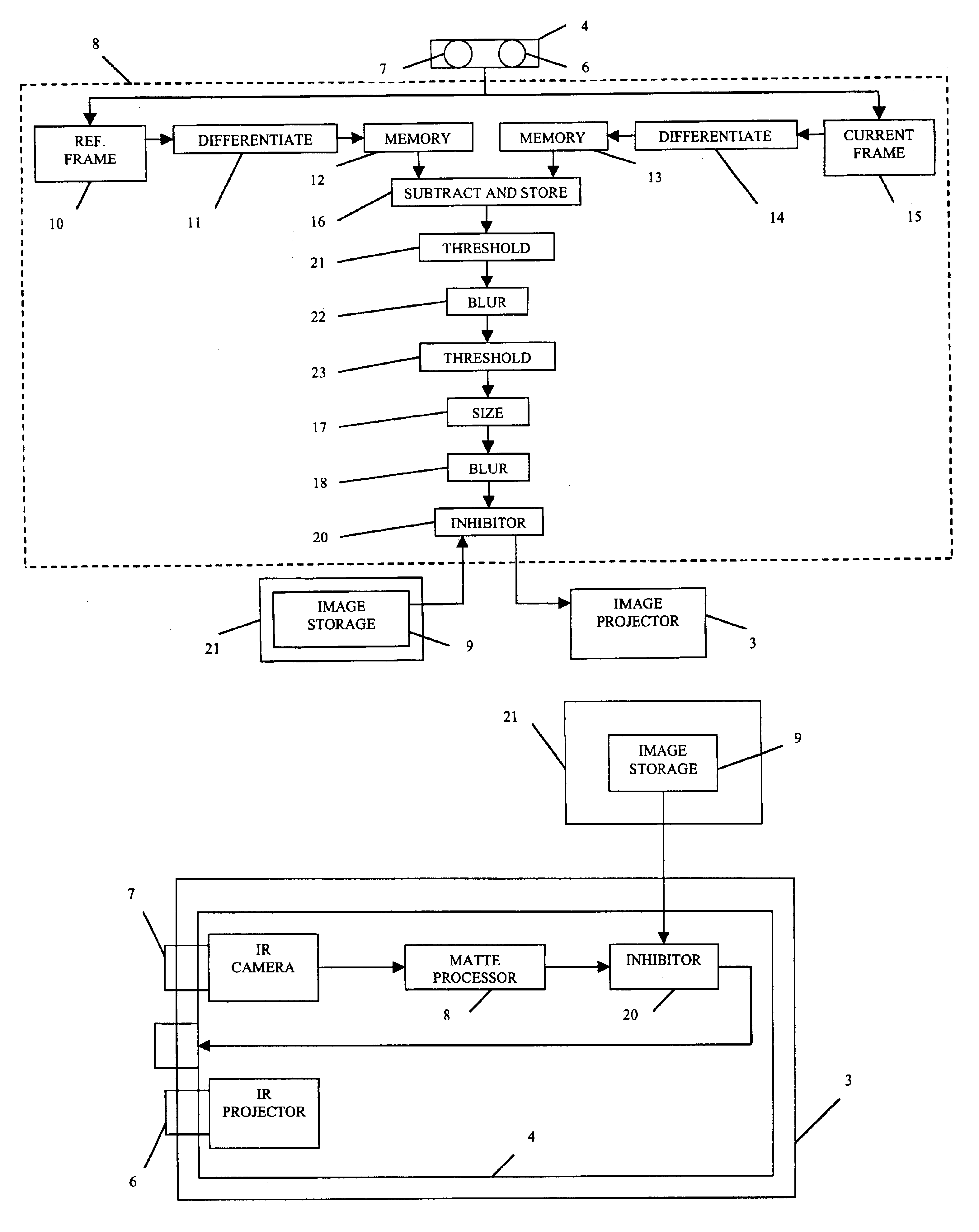
The functions of image storage (10,15,12, 13), signal differentiation (11,14), signal subtraction (16), blurring and sizing (17,18,22), greater than and less than comparison (21,23), and multiplication (20) are well known computer functions. The infrared projector 6 may be a film slide projector equipped with an incandescent lamp and incorporating a dichroic or other glass filter to reflect or absorb visible light. The infrared camera 7 may be any small video camera with dichroic or gelatin filter to reflect or absorb visible light. The video projector 3 may be any video projector receiving a video signal. The unique pattern may be a bandwidth limited random noise pattern, or a pattern simulating a bandwidth limited random noise.

The required computational functions listed above, if not performed in computer 21, are performed by programmable devices such as field programmable logic devices, or digital signal processors available from a variety of sources, the programming of which is ...


PUM


Abstract

A pattern is projected onto a screen by a projector using an illumination having a non-visible wavelength. A camera, displaced several inches from the projector, observes the projected pattern whose signals are then stored to create a reference frame. The pattern is then projected onto the screen a second time with a presenter present. The camera observes the projected pattern whose signals are then stored to create a current frame, including the presenter, and signals obtained from the reference frame are compared to determine their difference. In unobscured screen areas, the pattern images match. The pattern on the presenter is displaced because of the displaced camera, and no longer matches the reference pattern, thereby identifying the presenter's silhouette area.

Description

That portion of an image being projected onto a presenter in front of a projection screen is distorted and very distracting to both an audience and a presenter. U.S. Pat. No. 6,361,173 describes a method for generating a matte (alpha) signal to selectively inhibit the projected image in the screen area occupied by a presenter. A presenter may then walk in front of the screen and look at his audience without being blinded by the projector.The screen and presenter are illuminated with infrared light, and observed with an infrared camera. The pixel levels of a stored infrared screen-image when subtracted from the camera image of the screen with presenter present are zero in the unobscured screen area. All other pixels should be in the silhouette area of the presenter. Several other methods are described for locating the position of the presenter.The increased infrared illumination from opening a door or adjusting room illumination can result in a failure to generate a useable matte; al...

Claims


Application Information

Patent Timeline
Patent Type & Authority Patents(United States)
IPC IPC(8): G03B21/26G03B21/00G03B21/14H04N5/74H04N17/00
CPCH04N5/74G03B21/26G03B21/00
Inventor PARKER, JOSEPHVLAHOS, PAULDADOURIAN, ARPAGBERMAN, ARIE
Owner IMATTE INC
Why Eureka
Try Eureka